Project files
18 KB
Machine-translated by Robotheca from the original in Japanese (opens in a new tab). License: CC-BY-SA-4.0 (opens in a new tab).
〈2nd Gen.1〉KOROBO (2.1 Gen)
[!IMPORTANT] Except for the assembly instructions, all other data has been completed to a minimum level!
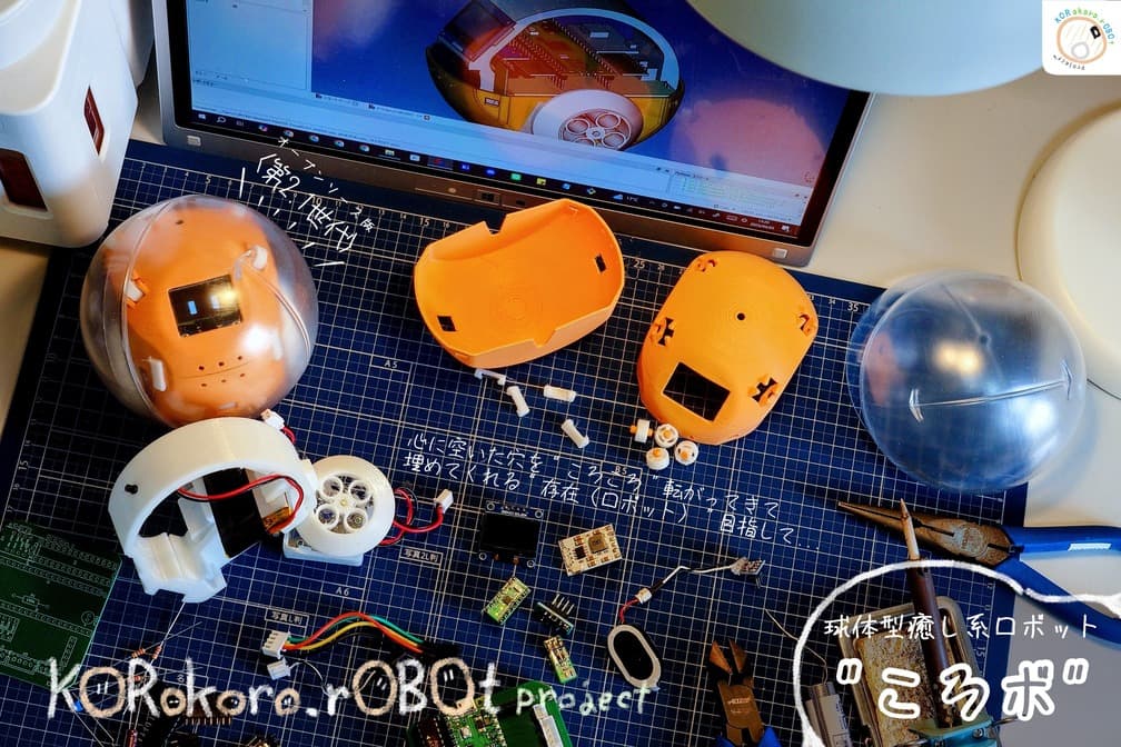
Overview / Overview
Korobo?
"Korobo" is a palm-sized robot enclosed in a capsule. Its face consists of two square eyes, and it moves forward, backward, left, and right inside the capsule, though it is tossed around by the round capsule. It doesn't speak any real words.
At first glance it seems a bit clumsy, but it has a strange charm: its delicate reactions to itself and its surroundings, and the interpretations people form precisely because it is imperfect and free of the designer's intentions.
And although it openly shows that it is a robot, we hope it becomes a new kind of being that somehow feels like one of us.
2nd Gen.1
Korobo 2.1 is an open-source version of the Korobo 2nd Gen, currently in development.
I think of it as a platform for making my philosophy and concept for robots clearer. At the same time, I hope that many people will take Korobo in a wide variety of directions.
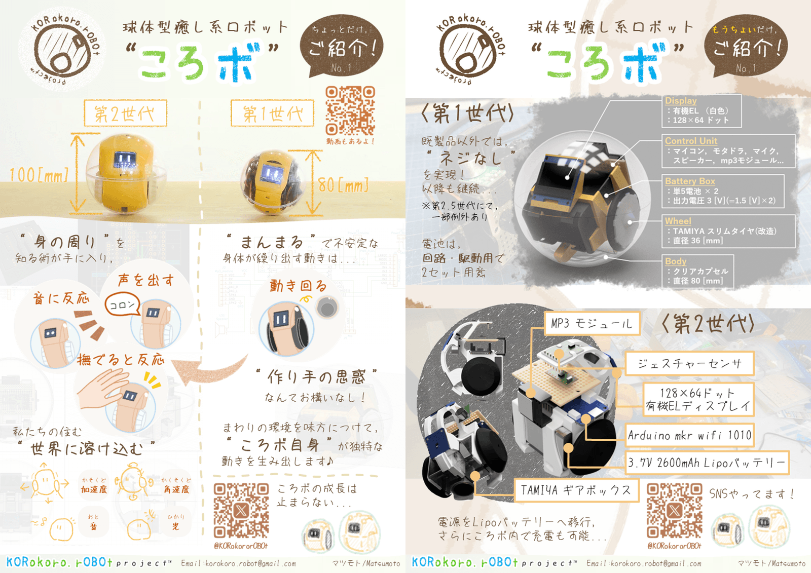
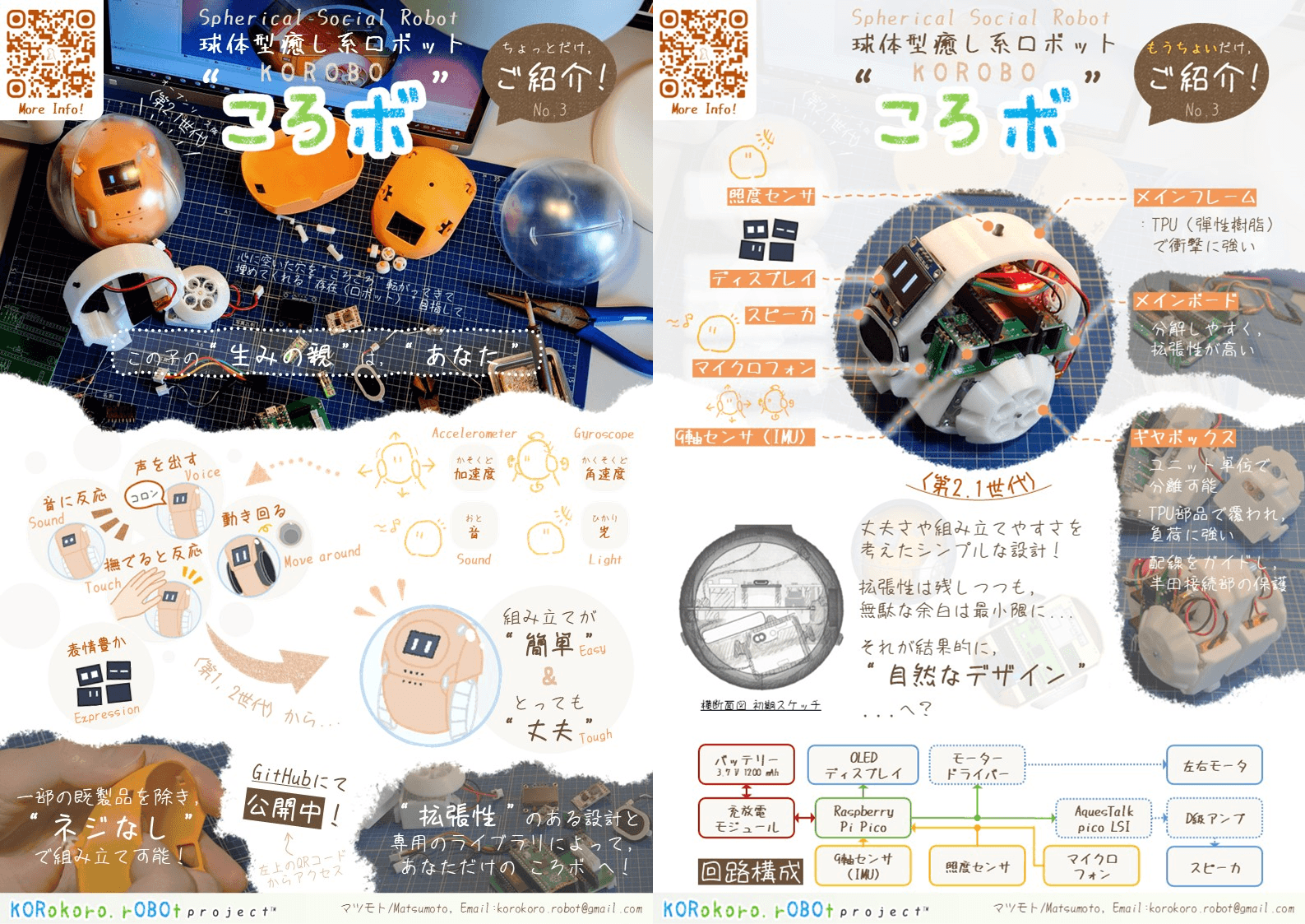
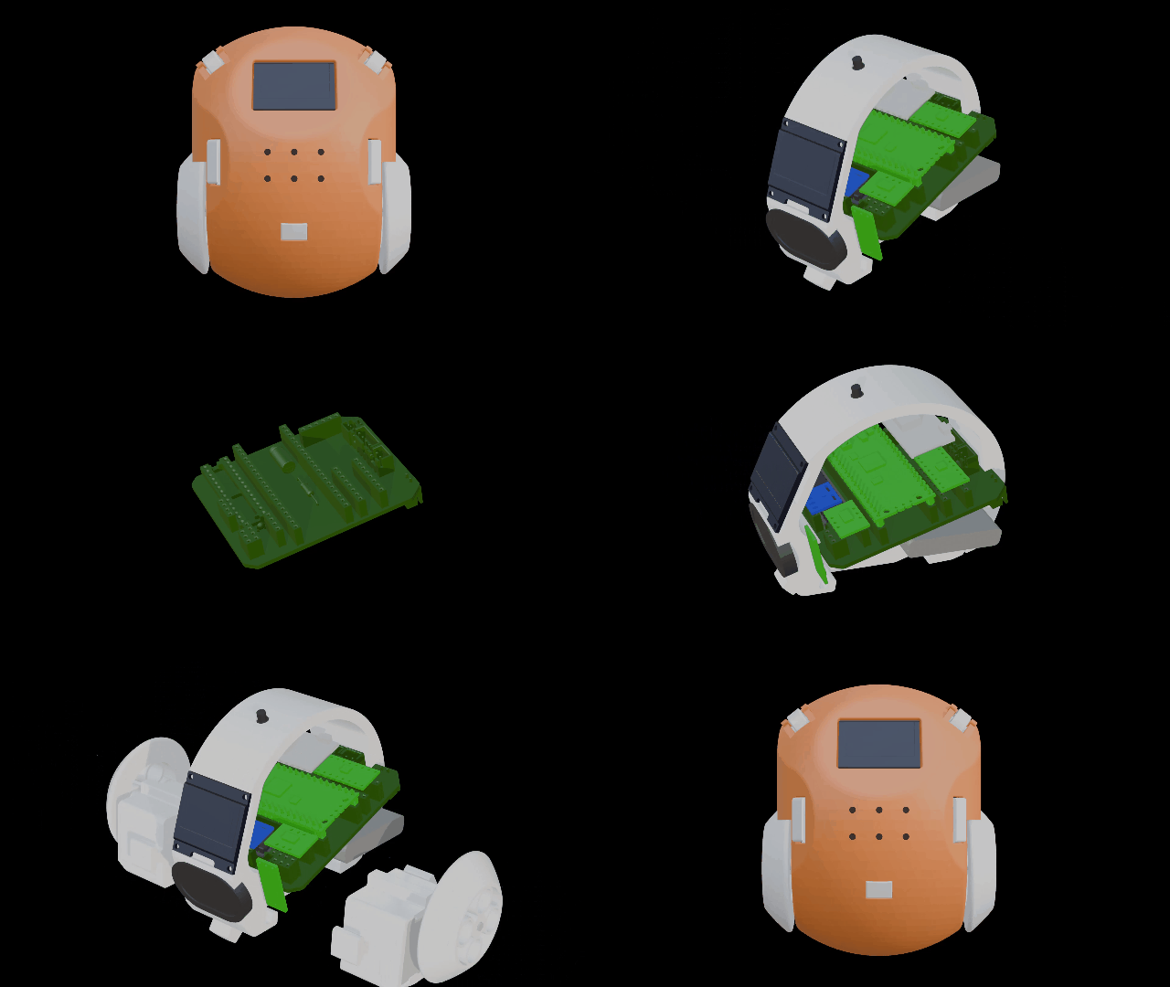
- Korobo keeps the simple structure and snap-fit assembly method1 that have been treasured since its early development, while improving durability and extensibility!
Even if it falls off a desk or gets accidentally kicked, it won't suffer fatal damage.
It has a microcontroller board and accessible space, so you can evolve it however you like.
- The microcontroller board is the Raspberry Pi Pico (opens in a new tab) provided by the Raspberry Pi Foundation!
It is inexpensive, easy to obtain, and has many building examples.
Many compatible boards exist, so you can choose freely based on USB port and purpose.
Like the Raspberry Pi Pico 2, it stays compatible even as generations advance.
Footnotes
-
既製品のギヤボックスキットは除く。 ↩
Assembly / How to Set Up
0.1 Procurement
Please source the various materials listed in the Document from the online stores or physical shops linked there.
0.2 Printing
[!TIP] If you have procured the 3D-printed parts from the KORokoro.rOBOt project's BOOTH (opens in a new tab), proceed to "0.3 Ordering or Making the PCB".
0.20 Preparation
0.21 PLA
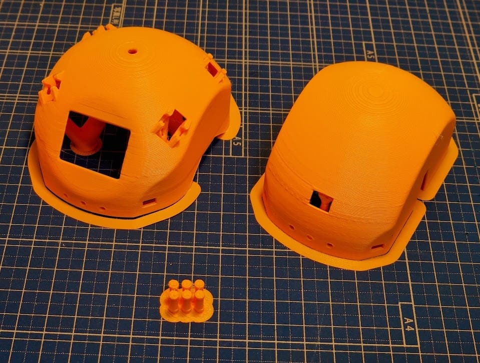
0.22 TPU
0.3 Board ordering or fabrication
[!TIP] If you have obtained the main board from the KORokoro.rOBOt project's BOOTH (opens in a new tab), please proceed to "1. Drive Unit".
Please upload the zip file inside Board to a PCB service site.
In preparation...
1.0 Preparation
Please prepare the tools and parts shown in the following table.
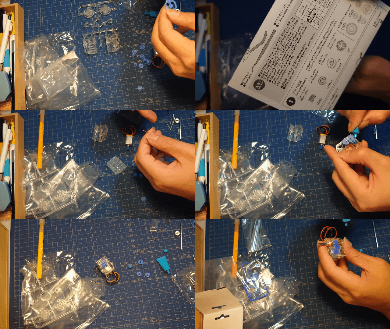
1.1 Gearbox
Assemble the mini-motor low-speed gearbox (4-speed) according to the included assembly instructions.
[!NOTE]
- Use a gear ratio of "149.9:1".
- Use the "38 [mm]" hex shaft included in the 3 mm hex shaft set.
- Do not use "L2" from the included instructions item ⑥, or the "crank plate" from item ⑦.
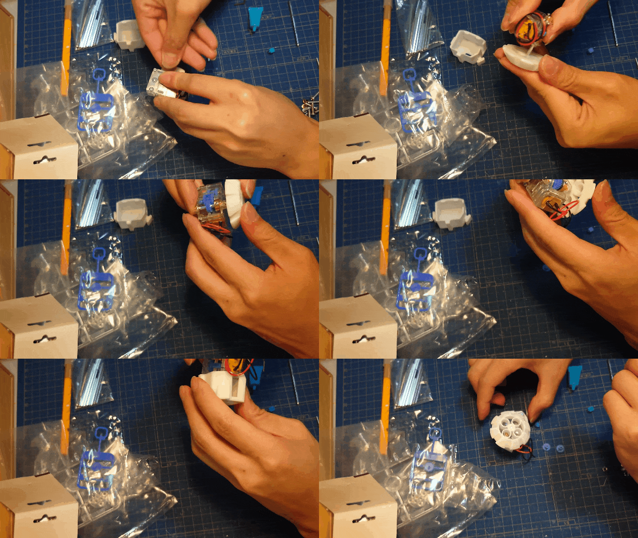
1.2 Tires & Covers
[!NOTE] When finally placing the parts into the capsule, you will need to fine-tune how tightly they are press-fitted.
-
Press-fit the procured main tires onto the gearbox shafts.
-
Fit the procured gearbox covers onto the gearbox.
2. Wiring (0/1/2/3/4/5)
[!TIP] If you have procured the wiring components from the KORokoro.rOBOt project's BOOTH (opens in a new tab), please proceed to "3. Circuit Board". (※Currently in preparation)

2.0 Preparation
Please prepare the tools and parts shown in the following table.
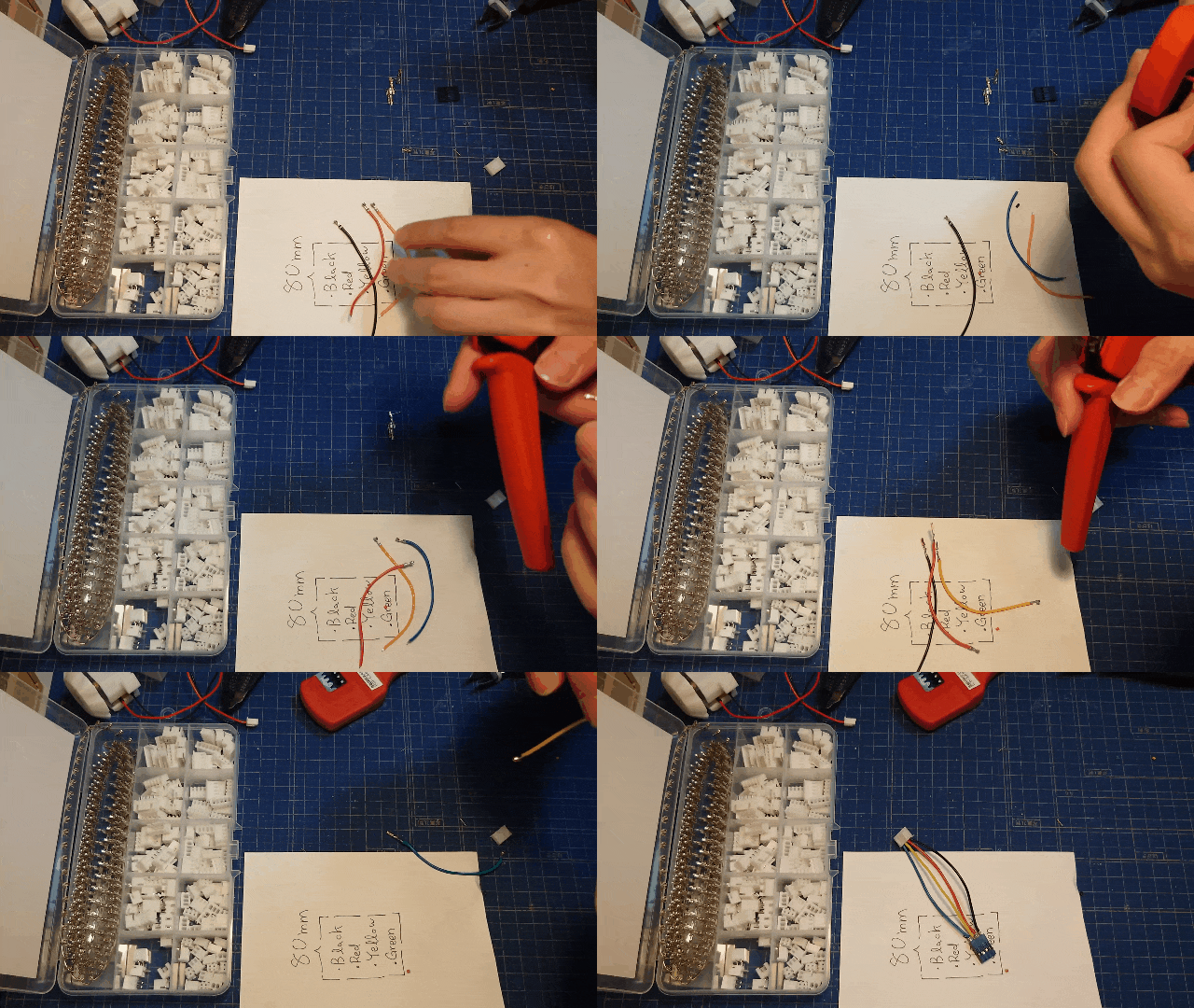
2.1 Drive Unit (JST-XH)
Motor (2P) ← Wires (black, red) → JST-XH (2P)
2.2 Light Sensor (JST-XH, Pin Socket)
JST-XH (2P) ← Wiring (black, other colors *1) → Pin socket (2P)
2.3 Display (JST-XH, pin socket)
JST-XH (4P) ← wiring (black, red, other colors *2) → pin socket (4P)
2.4 Speaker (PicoBlade)
Class-D amplifier (2P) ← wire (black, other color *1) → PicoBlade (2P)
3.0 Preparation
Please prepare the tools and parts shown in the following table and image.
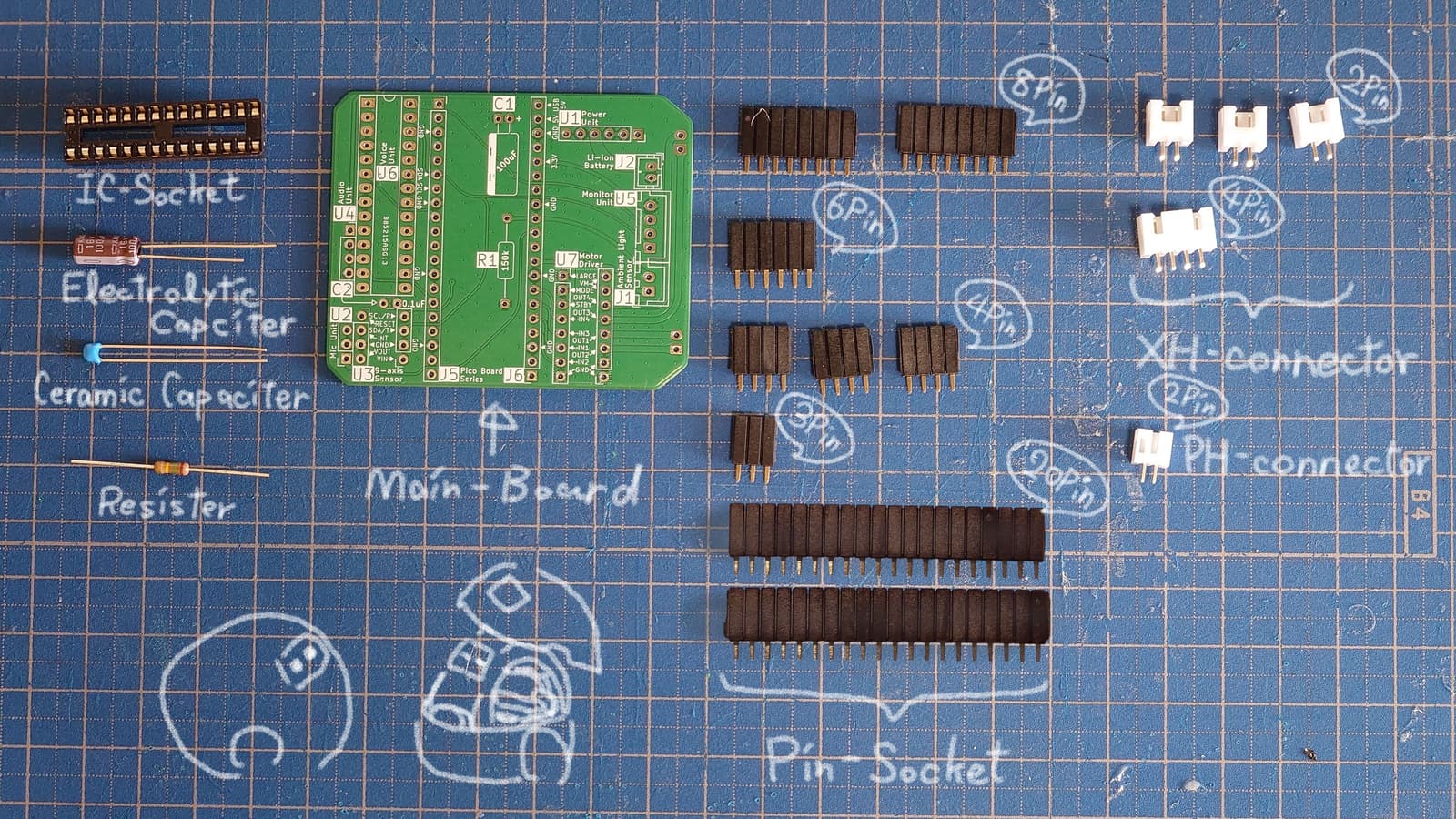
3.2 Soldering
[!IMPORTANT] The pin headers included with the module differ in length, so using separately sourced pin headers is recommended
-
Main board
Uncut version of the work process >> Click or tap (opens in a new tab)
Soldering order: Resistor/Capacitor → IC socket → XH/PH connector → Pin socketIn preparation...
-
Module
In preparation...
4.0 Preparation
Please prepare the tools and parts shown in the following table.
4.1 Modules (in order)
[!IMPORTANT] It is recommended to cover the part of the battery close to the board several times with vinyl tape or similar.
- Board << wiring
- Main frame << board (+ wiring)
- Main frame << battery
- Main frame << drive unit
4.2 Modules (in no particular order)
[!NOTE] Please pay attention to the orientation when connecting the pin socket (4P) to the OLED module. The GND pin and the black wire are a pair!
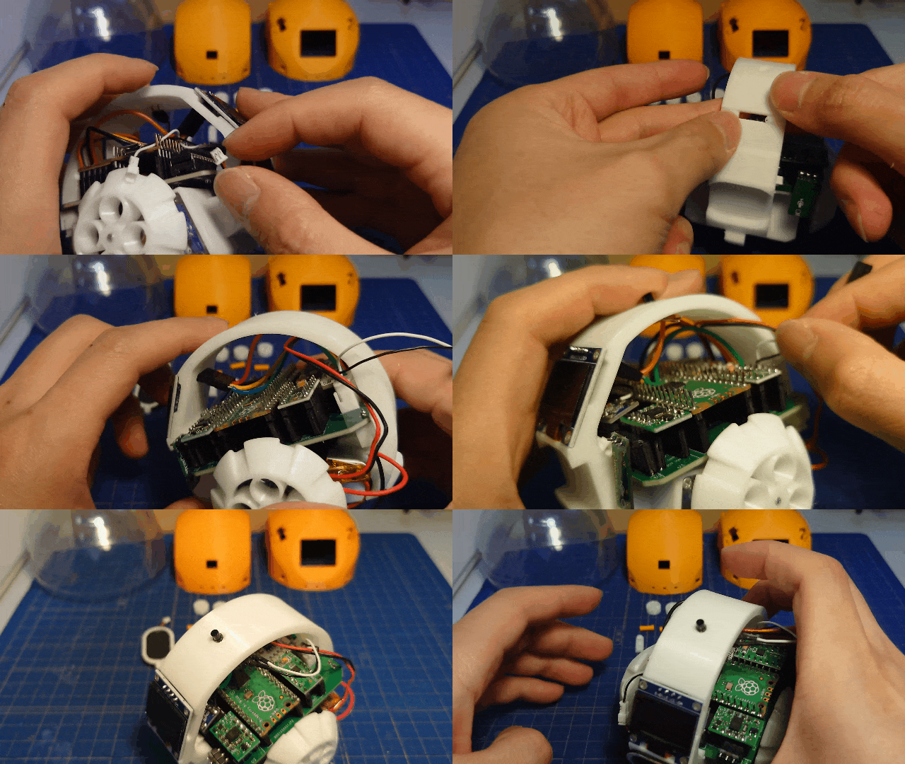
- Main frame << OLED, light sensor, speaker
4.3 Cover & Capsule
5.0 Preparation
Prepare the tools and parts shown in the following table.
[!NOTE] For the USB cable, use one with a connector type (plug shape) compatible with both the "PC" and the "ころボ microcontroller board."
5.1 Wiring
Work in progress...
5.2 Writing
Work in progress...
Life with KOROBO / Life with KOROBO
Charging
Connect a 5V output microUSB cable to the USB port on the right side of the Korobo.
Others
[!CAUTION]
- Uses a lithium-ion battery. Please handle with care.
- Due to the capsule's design, it is not fully waterproof.
- Any issues related to ころボ are at your own risk.
Files by @KORokoro-rOBOt-project, at commit 16168ac, read from GitHub in your browser. Hardware license: CC-BY-SA-4.0; software license: CC-BY-SA-4.0. Robotheca doesn't review code: read it before running it.