Project files
- PCB-DATA_korobo_2-1_bno055_ver3-1.zip306 KB
- PCB-DATA_korobo_2-1_bno055_ver3-2.zip313 KB
- README.md3 KB
- schematic_korobo_2-1_bno055_ver3-1.pdf155 KB
- schematic_korobo_2-1_bno055_ver3-2.pdf159 KB
README.md
Machine-translated by Robotheca from the original in Japanese (opens in a new tab). License: CC-BY-SA-4.0 (opens in a new tab).
Board
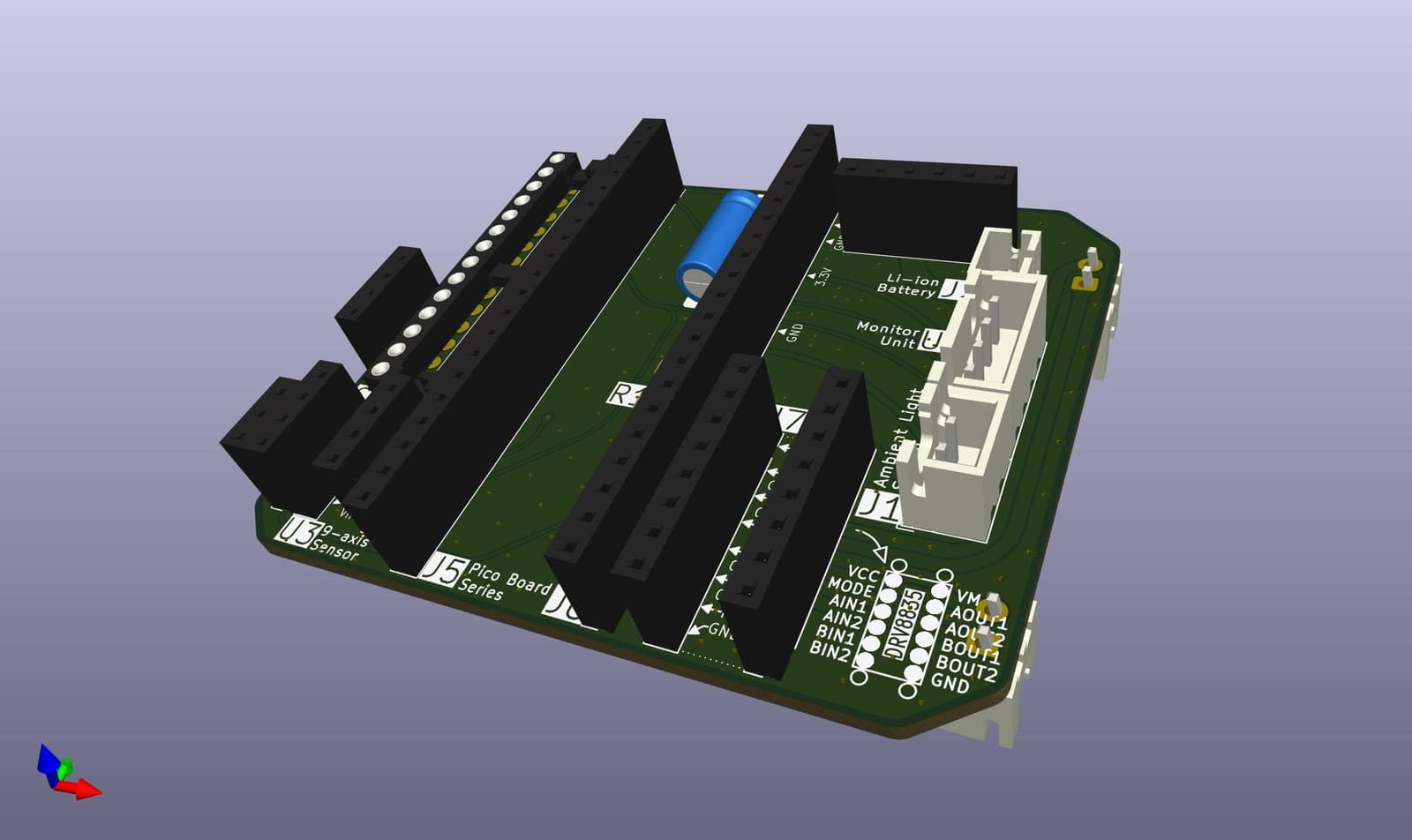
Overview / Overview
The printed circuit board of Korobo (2nd generation) focuses on ease of assembly and maintainability.
-
Compatibility with universal boards (2.54mm)
The pitch of all through-holes provided on the printed circuit board is 2.54mm. In other words, it is compatible with commercially available universal boards, so even those who have difficulty procuring printed circuit boards can build it (in theory...).
-
Connection via pin sockets and pin headers
The main board and various modules are connected by pin sockets and pin headers. Therefore, they can be easily removed, which allows flexible handling of failures and replacement of the microcontroller board.
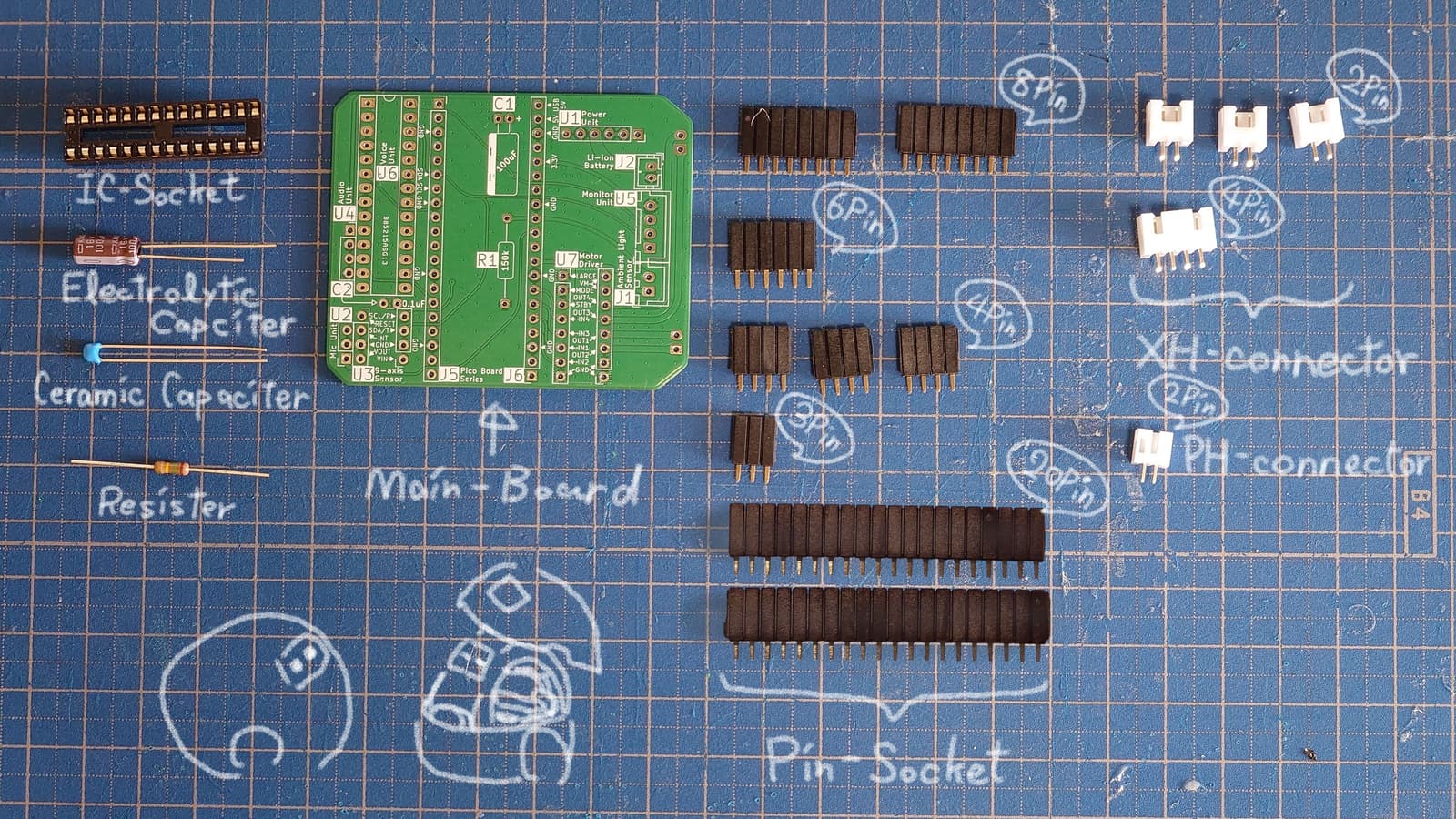
Parts List / 部品リスト
| Label | Specification | Qty | Notes |
|---|---|---|---|
| C1 | 100uF | 1 | Electrolytic capacitor |
| C2 | 0.1uF | 1 | Ceramic capacitor |
| J1 | JST XH 2pin | 1 | Connects to the light sensor |
| J2 | JST PH 2pin | 1 | Connects to the battery |
| J3 | JST XH 2pin | 1 | Connects to the right motor |
| J4 | JST XH 2pin | 1 | Connects to the left motor |
| J5 | PinSocket 2.54mm 20pin | 1 | Connects to the microcontroller board |
| J6 | PinSocket 2.54mm 20pin | 1 | Connects to the microcontroller board |
| R1 | 150k | 1 | Resistor |
| U1 | PinSocket 2.54mm 6pin | 1 | Connects to the charge/discharge module |
| U2 | PinSocket 2.54mm 3pin | 1 | Connects to the microphone sensor |
| U3 | PinSocket 2.54mm 4pin | 2 | Connects to the 9-axis sensor |
| U4 | PinSocket 2.54mm 4pin | 1 | Connects to the class-D amplifier |
| U5 | JST XH 4pin | 1 | Connects to the OLED |
| U6 | DIP-28 W7.62mm | 1 | Connects to the voice IC |
| U7 | PinSocket 2.54mm 8pin | 2 | Connects to the motor driver |
Files by @KORokoro-rOBOt-project, at commit 16168ac, read from GitHub in your browser. Hardware license: CC-BY-SA-4.0; software license: CC-BY-SA-4.0. Robotheca doesn't review code: read it before running it.