〈第2.1世代〉ころボ / KOROBO (2.1 Gen)
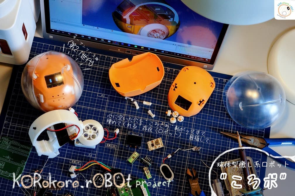
A palm-sized capsule-covered spherical robot with square eyes that rolls around inside its capsule and reacts to sound, light, and motion.
- Other
- Open source
- Work in progress
- arduino
- 3D printable
Suggested by Robotheca, created by @KORokoro-rOBOt-project (opens in a new tab), from github.com/KORokoro-rOBOt-project/KOROBO_2-1 (opens in a new tab). Pinned to commit 16168ac (opens in a new tab).
- Hardware license
- CC-BY-SA-4.0 (opens in a new tab)
- Software license
- CC-BY-SA-4.0 (opens in a new tab)
- Commercial use
- Allowed
Photo and 3D model
3D preview converted from github.com/KORokoro-rOBOt-project/KOROBO_2-1 at 16168ac, under CC-BY-SA-4.0. View the original files from GitHub (10.1 MB) (opens in a new tab)
- Cable length
- 10 cm
What it can do
Written by Robotheca from the project's documents.
- Palm-sized spherical robot with two square eyes shown on an OLED display, rolling by moving inside a capsule.
- Default behavior uses x and y accelerometer data to keep its wheels driving the body toward a level posture.
- Eye display can show sound, motion (IMU), or light information, individually or combined.
- Eye and voice can react to microphone, light sensor, and 9-axis IMU data.
- Speaks through a speech synthesis chip, sending text strings in AquesTalk pico format.
- Has a sleep function that pauses some behaviors based on sensor conditions (still being adjusted).
Bill of materials
This repository has no parts list Robotheca can read yet.
Build guide
The creator's steps, each with its instructions.
- 1Procure parts from the listed vendors
- 2Print 3D-printed parts (PLA and TPU) and remove supports
- 3Order or fabricate the main board from the Gerber data
- 4Assemble the drive unit: gearbox, tires and covers
- 5Make the wiring harness with crimped JST-XH, JST-PH, PicoBlade and pin sockets
- 6Solder the main board components
- 7Assemble the module: board, main frame, battery and drive unit
- 8Attach the OLED, light sensor and speaker to the main frame
- 9Fit the cover and capsule
- 10Connect the USB cable and write the software to the microcontroller
The guide appears here as you scroll.
Guide by @KORokoro-rOBOt-project (README.md), under CC-BY-SA-4.0. The English translation is by Robotheca, shared under the same license.
More guides
Wiring and electronics
Notes written by Robotheca from the project's documents.
Main parts
- Raspberry Pi Pico microcontroller board (the documents say other compatible boards can be swapped in).
- TC78H653FTG or DRV8833 motor driver module for the two geared motors.
- Tamiya mini-motor low-speed gearbox motors, one per wheel.
- 0.96-inch 128x64 white OLED display for the eyes.
- Silicon microphone module (SPV1840LR5H-B) for sound input.
- Light sensor (NJL7302L-F3) for ambient brightness.
- Speech synthesis LSI ATP3011F1-PU with a PAM8012 class-D amplifier and speaker.
- Lithium-ion battery with a charge/discharge module, charged through a microUSB port on the right side.
- Passives: 100uF electrolytic and 0.1uF ceramic capacitors, a 150k resistor.
Connections
- Motors connect to the main board via JST-XH 2-pin connectors (one per motor).
- Light sensor connects through a JST-XH 2-pin connector to pin sockets.
- OLED display connects through a JST-XH 4-pin connector to pin sockets.
- Speaker amplifier connects through a PicoBlade 2-pin connector.
- Battery connects through a JST-PH 2-pin connector.
- The microcontroller board plugs into two 20-pin sockets on the main board, so it can be swapped.
- The voice chip sits in a DIP-28 socket; sensor and driver modules plug in through pin sockets.
- Pin sockets and headers let modules be removed for repair or board replacement.

