Spot Micro - Leika
An open-source ESP32-based quadruped robot with a web-based controller and a MuJoCo simulator.
- Quadruped
- Open source
- arduino
- 3D model (URDF)
- 3D printable
Suggested by Robotheca, created by @runeharlyk (opens in a new tab), from github.com/runeharlyk/SpotMicroESP32-Leika (opens in a new tab). Pinned to commit 2b594d6 (opens in a new tab).
- Hardware license
- MIT (opens in a new tab)
- Software license
- MIT (opens in a new tab)
- Commercial use
- Allowed
This repository contains executable files that Robotheca doesn't check. Only run them if you trust the creator.
Which files (1 firmware image)
Photo and 3D model
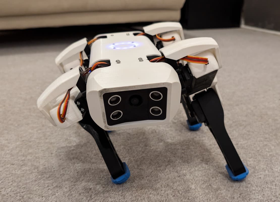
3D preview converted from github.com/runeharlyk/SpotMicroESP32-Leika at 2b594d6, under MIT. View the original files from GitHub (4.1 MB) (opens in a new tab)
- Degrees of freedom
- 3
What it can do
Written by Robotheca from the project's documents.
- Quadruped robot with 12 servos, three degrees of freedom per leg, controlled by inverse kinematics on an ESP32.
- Walks with a 12-point Bezier trot or an 8-phase crawl gait, plus static and dynamic posing.
- Controlled from a self-hosted SvelteKit web interface with dual joysticks and a real-time 3D view.
- Streams telemetry of every control tick over WebSocket and USB serial.
- A MuJoCo simulation with a Python Robot API that runs the same calls on the simulation or the real robot.
Bill of materials
This repository has no parts list Robotheca can read yet.
Build guide
The creator's steps, each with its instructions.
- 1Review components and bill of materials
- 2Assemble the robot
- 3Install the software
- 4Configure the robot
- 5Run the robot
The guide appears here as you scroll.
Guide by @runeharlyk (readme.md), under MIT.
More guides
Wiring and electronics
Notes written by Robotheca from the project's documents.
Main parts
- ESP32 microcontroller as the main controller.
- PCA9685 servo driver board, 12 servos.
- DC-DC converter and a 2S battery.
- Optional gesture sensor and camera.
Connections
- The PCA9685 and the IMU share the ESP32's I2C bus; the PCA9685 uses address 0x40.
- Default SDA and SCL pins depend on the board environment, for example GPIO 21 and 22 on esp32dev.
- Servo channels 0 to 11 on the PCA9685, with joint j on channel j by default.
- The circuit schematic is in docs/media/circuitschematic.png.


