← 12-DOF Quadruped Robot
Project files
- README.assets6 files
- 三维模型6 files
- 动力学仿真80 files
- 单片机控制代码1086 files
- 参考资料2 files
- 模型演示动画1 file
- 蓝牙模块3 files
- LICENSE11 KB
- README.md3 KB
README.md
Machine-translated by Robotheca from the original in Chinese (opens in a new tab). License: Apache-2.0 (opens in a new tab).
Quadruped Robot
12-DOF quadruped robot design driven by servos
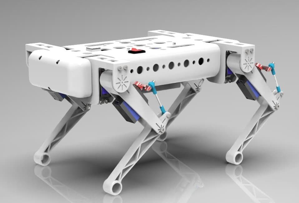
1. Structural Design
- The robot's overall dimensions are approximately 400mm × 230mm × 180mm, with a weight of around 2kg.
- The robot has 12 degrees of freedom, with each joint driven by a servo motor. To save space, the lower leg joints are indirectly driven by a linkage mechanism.
- To reduce the weight of the body and shorten the processing time, the design features an integrated structure with extensive hollowed-out sections. All parts are either 3D printed or purchased from Taobao.
- For design details, refer to the contents of the
三维模型(3D Models) folder, which includes two iterative versions of the model. - Software used:
Solidworks,AutoCAD,Keyshot.
2. Gait Algorithm
- Due to the performance limitations of the servos, the gait control of this robot is open-loop only, meaning it uses the most common inverse kinematics solution (for more details, refer to the book Robotics or relevant Zhihu answers). There is still significant room for improvement in gait stability.
4. Dynamic Simulation
- The dynamic simulation is based on
ADAMSandMatlab, primarily completing simple gait simulations of the quadruped robot on flat ground and slopes - Brief simulation steps:
- Inverse kinematics is achieved through
Simulink, and joint angle curves over time are solved based on the set foot-end trajectory function - After extracting the data, it is imported into
ADAMSto create spline curves, which serve as the respective joint drives - In
ADAMS, parameters such as contact force and friction are set to achieve the robot's gait simulation
- Inverse kinematics is achieved through
- For detailed content, refer to parts of the
动力学仿真folder - Software used:
ADAMS,Matlab
5. Hardware System Design

- The STM32F103 serves as the control board, equipped with a gyroscope module for IMU stabilization and a Bluetooth module for real-time communication, while an ultrasonic ranging module enables basic obstacle avoidance.
- The entire robot is powered by a 3300mAh lithium battery, divided into two circuits:
- One circuit powers the servos via a UBEC independent power module to ensure stable voltage and current.
- The other powers the microcontroller using an LM2596 buck converter for voltage regulation.
6. Software System Design
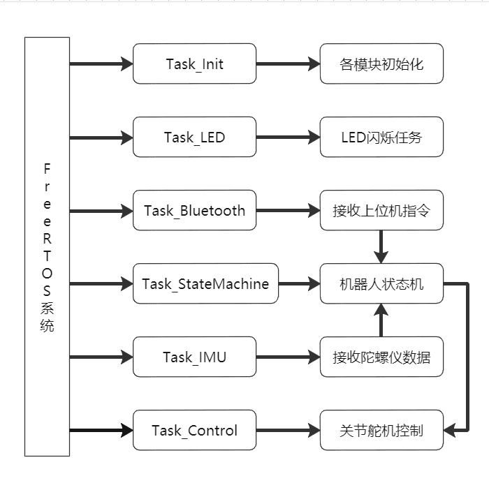
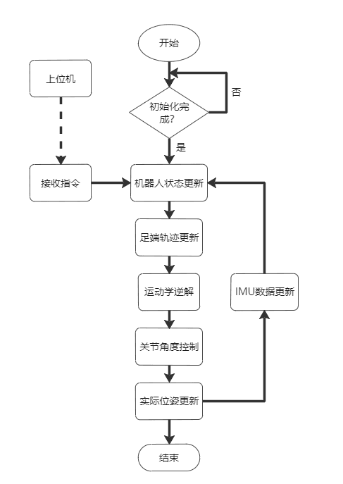
- The system is primarily implemented using the
FreeRTOSoperating system based onSTM32, with the task allocation and scheduling shown in the left diagram above. - The control logic of the entire robot is shown in the right diagram above.
- For implementation details, refer to parts of the
单片机控制代码(Microcontroller Control Code) folder. - Software used:
Keil
6. Notes
- This project is an undergraduate thesis project. The design, modeling, assembly, and debugging were all completed by myself. Due to a lack of some professional knowledge and time constraints, there are many immature designs in various aspects. The entire project is for reference only.
- Prohibited from using this project for any commercial purposes.
- If you have any questions, feel free to discuss and exchange ideas.
Files by @lshil00, at commit 645aca7, read from GitHub in your browser. Hardware license: Apache-2.0; software license: Apache-2.0. Robotheca doesn't review code: read it before running it.