Zuko
A quadruped robot dog built on ROS2 with a Raspberry Pi 4, custom expansion board and a PlayStation 4 controller.
- Quadruped
- Open source
- Work in progress
- ROS 2
- 3D model (URDF)
- 3D printable
Suggested by Robotheca, created by @reubenstr (opens in a new tab), from github.com/reubenstr/zuko (opens in a new tab). Pinned to commit 0d6733c (opens in a new tab).
- Hardware license
- MIT (opens in a new tab)
- Software license
- BSD-3-Clause (opens in a new tab)
- Commercial use
- Allowed
This repository contains executable files that Robotheca doesn't check. Only run them if you trust the creator.
Which files (1 file marked executable)
Photo and 3D model
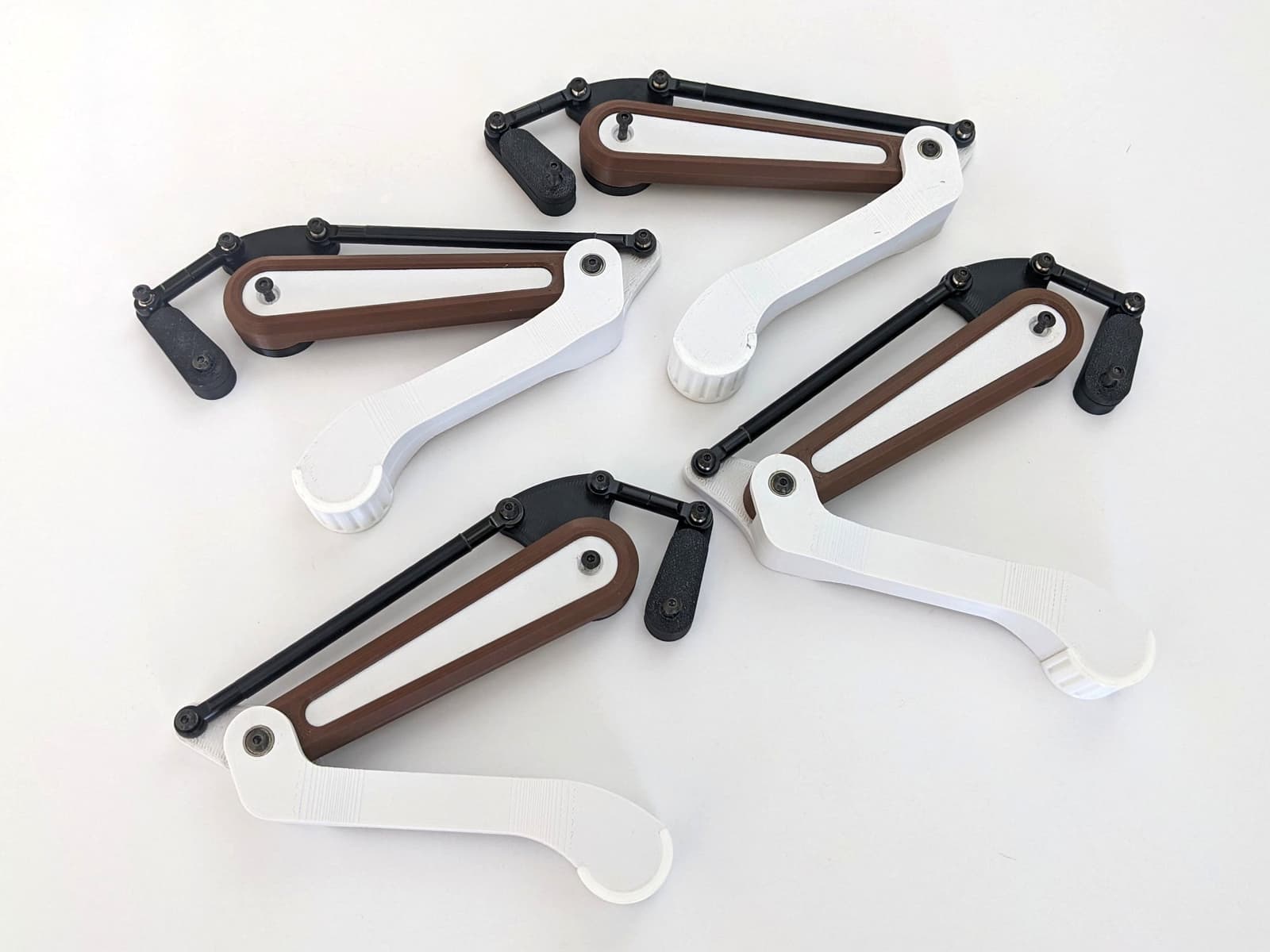
3D preview converted from github.com/reubenstr/zuko at 0d6733c, under MIT. View the original files from GitHub (3.8 MB) (opens in a new tab)
What it can do
Written by Robotheca from the project's documents.
- Quadruped robot dog that walks, controlled from a PlayStation 4 controller via a Raspberry Pi 4.
- Uses ROS2 for communication, launching, and third-party add-ons.
- Controls 12 RC servos for legs, plus auxiliary RC servos.
- Peripheral support planned or listed for IMU, foot touch switches, LEDs, NeoPixel strips, current and voltage sensing, and extra I2C devices.
- Frame v2.2 is being tested and is described as nearly ready for replication; the ROS2 workspace is still in development.
Bill of materials
This repository has no parts list Robotheca can read yet.
Build guide
The guide appears here as you scroll.
Guide by @reubenstr (README.md), under MIT (hardware) and BSD-3-Clause (software).
More guides
Wiring and electronics
Notes written by Robotheca from the project's documents.
Main parts
- Raspberry Pi 4 as the main computer.
- Custom expansion board with PWM and ADC controllers on I2C, connecting directly to the Raspberry Pi 4 (v1 prototype).
- Motor controller board built around a Teensy 4.0 microcontroller, which drives the servos and peripherals.
- Battery board holding 8x 18650 LiPo cells with 4x HY2120 (or similar) battery management systems.
- Requires an external DC-DC converter supplying 5V to the motor controller board and the Raspberry Pi.
Connections
- The motor controller board connects to and powers the Raspberry Pi.
- The expansion board connects directly to the Raspberry Pi 4 for servo and peripheral control without a microcontroller.
- Expansion boards use I2C for their PWM and ADC controllers.
Schematics, boards and diagrams
- pcbs/battery-board/battery-board.kicad_pcbKiCad
- pcbs/battery-board/battery-board.kicad_schKiCad
- pcbs/battery-board/gerbersGerber (PCB manufacturing)
- pcbs/battery-board/gerbers/gerbers.zipGerber (PCB manufacturing)
- pcbs/expansion-board/expansion-board-schematic.pdfDiagram
- pcbs/expansion-board/expansion-board.kicad_pcbKiCad
- pcbs/expansion-board/expansion-board.kicad_schKiCad
- pcbs/expansion-board/gerbersGerber (PCB manufacturing)
- pcbs/motor-controller/gerbers/gerbers.zipGerber (PCB manufacturing)
- pcbs/motor-controller/gerbersGerber (PCB manufacturing)
- pcbs/motor-controller/motor-controller.kicad_pcbKiCad
- pcbs/motor-controller/motor-controller.kicad_schKiCad
- pcbs/motor-controller/pcb-review-temp/pcb-schematic.pngDiagram
- pcbs/motor-controller/pcb-review-temp/zuko-teensy-motor-controller-schematic.pdfDiagram
