SpotMicro ESP32
A 3D-printable quadruped robot dog with support-free printed parts, controlled by an ESP32-DevKitC with heavy computation offloaded to external devices.
- Quadruped
- Open source
- arduino
- 3D printable
Suggested by Robotheca, created by @michaelkubina (opens in a new tab), from github.com/michaelkubina/SpotMicroESP32 (opens in a new tab). Pinned to commit 2f10e14 (opens in a new tab).
- Hardware license
- GPL-3.0-only (opens in a new tab)
- Software license
- GPL-3.0-only (opens in a new tab)
- Commercial use
- Allowed
Photo and 3D model
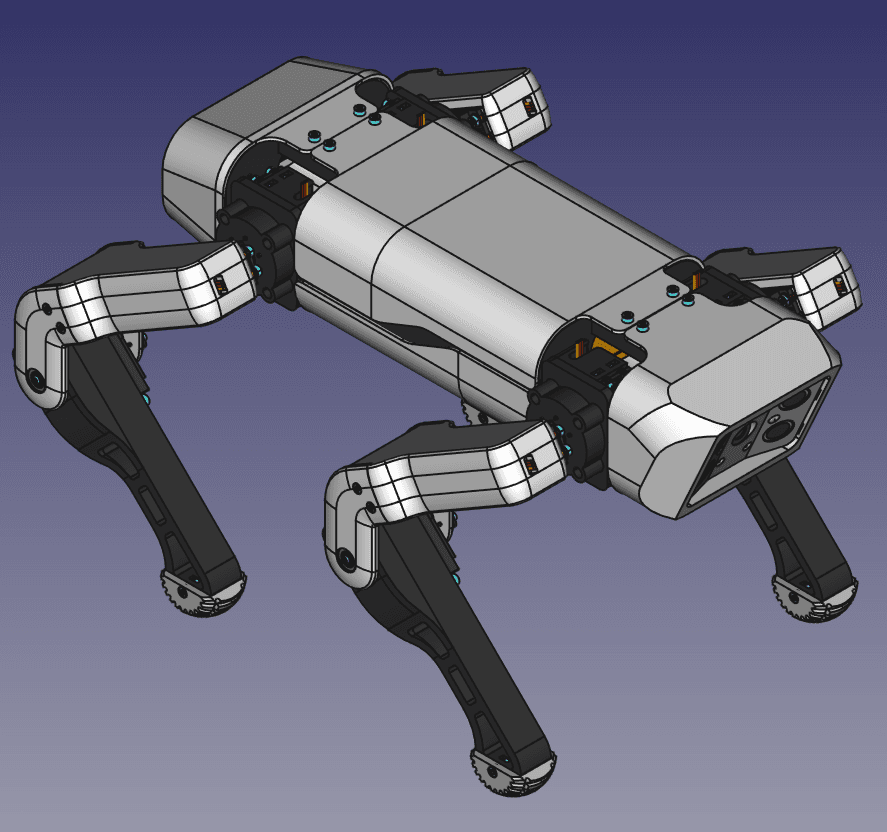
3D preview converted from github.com/michaelkubina/SpotMicroESP32 at 2f10e14, under GPL-3.0-only. View the original files from GitHub (9.4 MB) (opens in a new tab)
What it can do
Written by Robotheca from the project's documents.
- Quadruped SpotMicro-style robot with 12 servos, three per leg, on an ESP32 controller.
- Built around a 3D-printed design optimized for support-free printing.
- Status and mood signaled by a WS2812b LED ring and a 0.96 inch OLED display.
- Distance sensing via two HC-SR04 ultrasonic sensors and orientation sensing via a GY-521 gyroscope/accelerometer.
- Battery voltage and current monitored by a voltage sensor module and an ACS712 current sensor, which can support emergency shutdown.
- Head camera provided by an ESP32-CAM module with an OV2640 sensor.
- Servo power can be cut completely by a relay module.
Bill of materials
This repository has no parts list Robotheca can read yet.
Build guide
The guide appears here as you scroll.
Guide by @michaelkubina (README.md), under GPL-3.0-only.
More guides
Wiring and electronics
Notes written by Robotheca from the project's documents.
Main parts
- ESP32-DevKitC as the main microcontroller with WiFi and BLE.
- ESP32-CAM with OV2640 camera, flashed through an FT232RL USB-TTL adapter.
- 12 servos, such as MG996R or DS3218MG, with rubber dampeners and servo horns.
- PCA9685 16-channel 12-bit PWM board driving the servos and LEDs.
- WS2812b 12 LED ring, 0.96 inch SSD1306 OLED display over I2C.
- Two HC-SR04 ultrasonic sensors and a GY-521 gyroscope/accelerometer.
- HW-482 / KY-019 5V relay module to cut servo power.
- ACS712 30A current sensor and a 25V voltage divider sensor module.
- 2S LiPo battery (5200-6200mAh) as main power source.
- XL4016 or SZBK07 DC-DC step-down converter to 6.5V for servos, and an LM2596 or similar module to 5V for the ESP32 and modules.
- 19mm illuminated latching push button.
Connections
- Servos are driven through the PCA9685 PWM board, which can take power from an external source.
- Servo power is switched by the relay module, which cuts power to the servos completely.
- The LiPo 2S battery feeds the XL4016 or SZBK07 converter (6.5V for servos) and the LM2596 converter (5V for the ESP32 and modules).
- Micro-USB to DIP adapters extend the USB ports of the ESP32 DevKitC and ESP32-CAM.
- The ESP32-CAM is flashed via the FT232RL USB-TTL adapter.
- Official wiring is shown in Fritzing files and diagrams in the electronics folder.
Schematics, boards and diagrams
- assembly/images/021_chassis_sides_circuitboardmount_post.pngDiagram
- assembly/images/021_chassis_sides_circuitboardmount_pre.pngDiagram
- electronics/2020-02-03_Circuitry_final.fzzFritzing
- electronics/2020-02-03_Circuitry_final.pngDiagram
- electronics/2020-02-03_Circuitry_final.svgDiagram
- electronics/archive/2020-12-09_Circuitry_final.fzzFritzing
- electronics/archive/2020-12-09_Circuitry_final.pngDiagram
- electronics/archive/2020-12-09_Circuitry_final.svgDiagram
- electronics/circuitry_working.jpgDiagram
- parts/SpotMicroESP32_parts_v1_0_0/images/original/Circuitboard_Mount (Template).pngDiagram
- parts/SpotMicroESP32_parts_v1_0_0/images/original/Circuitry_Mountingplate (Template).pngDiagram
- parts/SpotMicroESP32_parts_v1_0_0/images/original/Circuitry_Mountingplate_SZBK07_Extended.pngDiagram
- parts/SpotMicroESP32_parts_v1_0_0/images/original/Circuitry_Mountingplate_SZBK07.pngDiagram
- parts/SpotMicroESP32_parts_v1_0_0/images/original/Circuitry_Mountingplate_XL4016_Extended.pngDiagram
- parts/SpotMicroESP32_parts_v1_0_0/images/original/Circuitry_Mountingplate_XL4016.pngDiagram
- parts/SpotMicroESP32_parts_v1_0_0/images/thumbs/Circuitboard_Mount (Template).pngDiagram
- parts/SpotMicroESP32_parts_v1_0_0/images/thumbs/Circuitry_Mountingplate (Template).pngDiagram
- parts/SpotMicroESP32_parts_v1_0_0/images/thumbs/Circuitry_Mountingplate_SZBK07_Extended.pngDiagram
- parts/SpotMicroESP32_parts_v1_0_0/images/thumbs/Circuitry_Mountingplate_SZBK07.pngDiagram
- parts/SpotMicroESP32_parts_v1_0_0/images/thumbs/Circuitry_Mountingplate_XL4016_Extended.pngDiagram
- parts/SpotMicroESP32_parts_v1_0_0/images/thumbs/Circuitry_Mountingplate_XL4016.pngDiagram
- parts/SpotMicroESP32_parts_v1_0_0/mods/rpi_zero_mountingplate/EXPERIMENTAL_Circuitry_Mountingplate_Extended_Raspberry_Pi_Zero_W.pngDiagram
- parts/SpotMicroESP32_parts_v1_0_0/mods/rpi_zero_mountingplate/EXPERIMENTAL_Circuitry_Mountingplate_Raspberry_Pi_Zero_W.pngDiagram


.png)
.png)


.png)
.png)


