Project files
README.md
Machine-translated by Robotheca from the original in Chinese (opens in a new tab). License: Apache-2.0 (opens in a new tab).
SCARA_Parallel
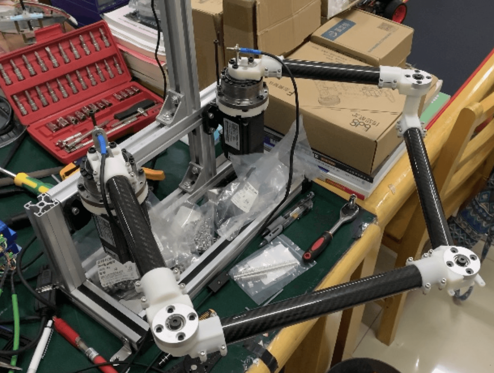
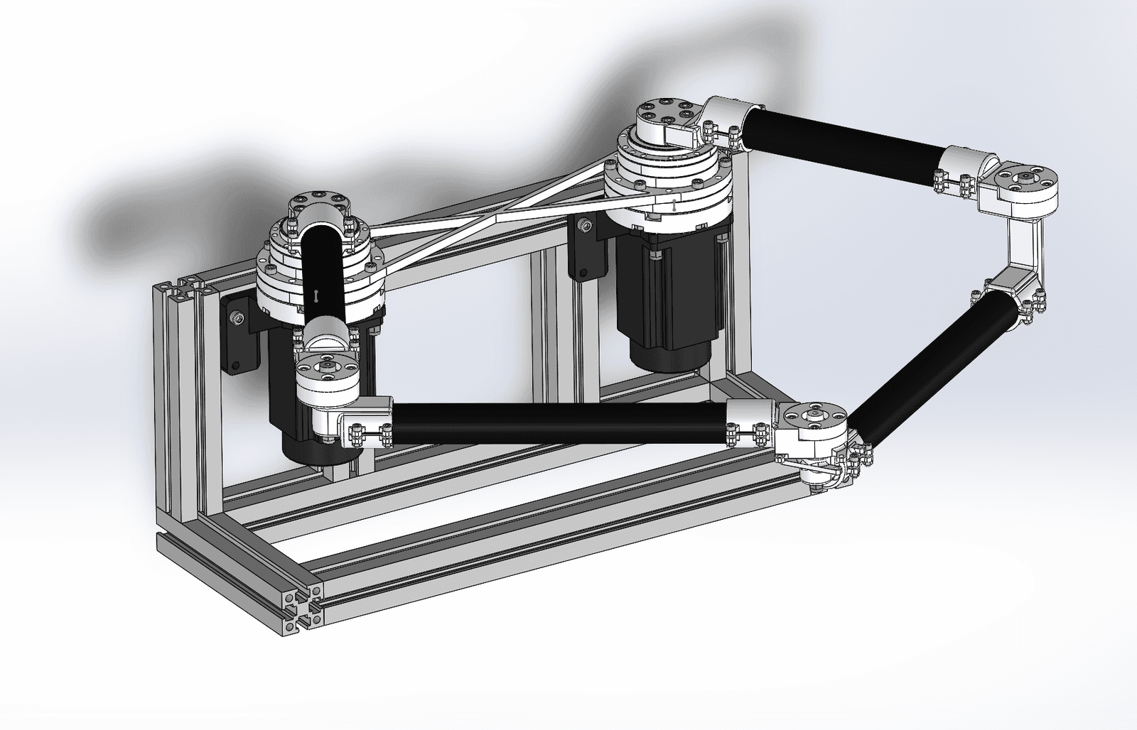
A parallel SCARA robotic arm designed for a graduation project, featuring closed-loop stepper motors, harmonic reducers, carbon fiber rods, 3D-printed joints, motion control, and linear interpolation.
Future updates will include MATLAB kinematic simulations, motion control code based on STM32F407, interpolation code, and sharing of design insights.
Update Notes
2023.9.11: Updated 3D models — all parts, motors, reducers, rods, machined shafts, 3D-printed joints, and assembly files.
1. Hardware Selection and Structural Design
1.1 Motor Selection
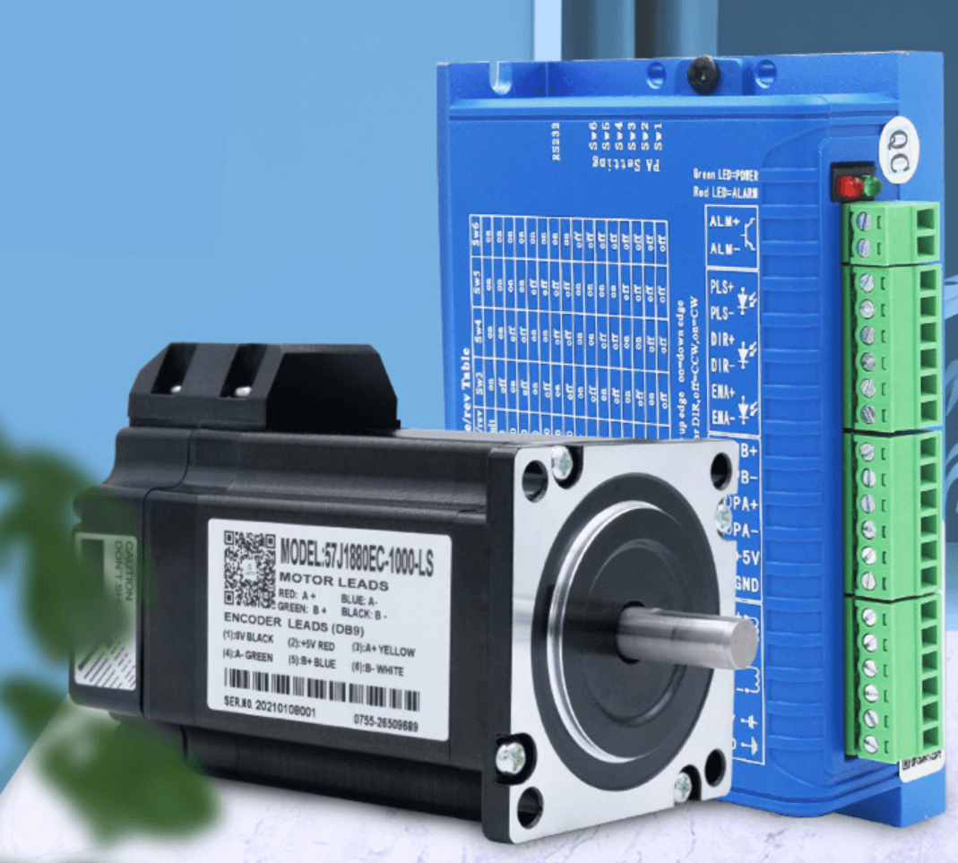
Due to cost and project workload considerations, servo motors or brushless motors were not chosen to drive the joints. Instead, closed-loop stepper motors were selected.
The motor model is the Jiemaikang 57J1880, purchased on Xianyu (a second-hand marketplace) for about 150 RMB per unit including the driver. The driver model is 2HSS57, also from Jiemaikang. It includes built-in motor control algorithms with current and position loops, making it as easy to control as a regular stepper motor driver — just send pulses.
In the future, if time permits, a brushless motor version with FOC control may be considered to enable dynamic control.
1.2 Reducers
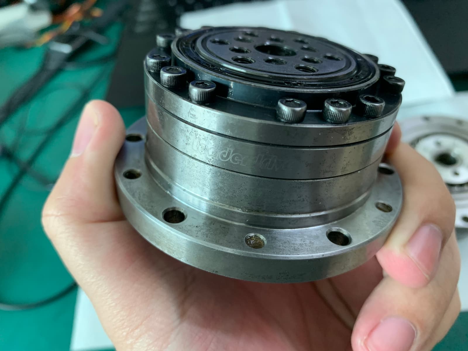
Harmonic reducers were chosen. The selected model is the green LSCG series from Leaderdrive, with a 17-50 size and a 50:1 reduction ratio, purchased for 450 RMB each. Since the motor output shaft and reducer input shaft sizes differ, a custom coupling was designed to thicken the motor shaft and insert it into the reducer's hole, secured with a key pin and set screw. The motor end already has a D-shaped shaft, so it fits directly. The 3D model includes all parts and assembly methods.
1.3 Joint Rotation Axle
This was the most challenging part since I'm not a mechanical engineering major. I had no idea how to design a rotating joint. Eventually, I found flange-mounted bearings, which made the design much easier.
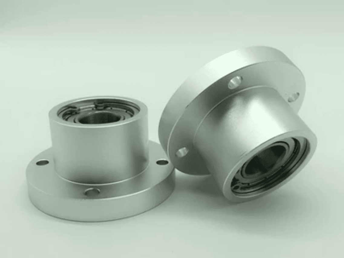
1.4 Rod Selection
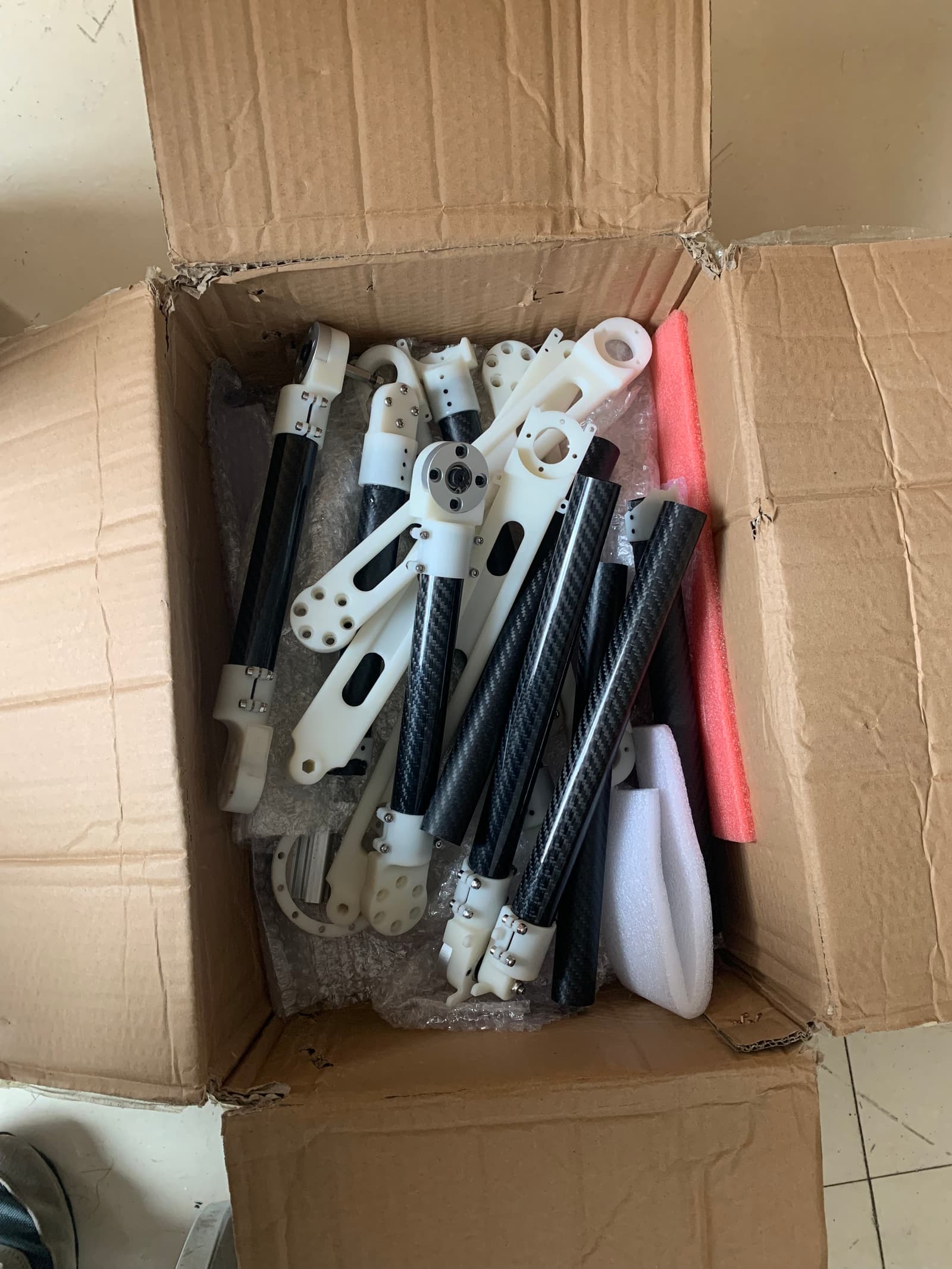
I went through many detours. At one point, the entire structure was printed using photopolymer resin, but the stiffness was completely insufficient — the structure sagged under its own weight. Later, the design switched to carbon fiber tubes. Below are the rods used; there was a whole box of them.
Files by @Yangtao123droid, at commit e250202, read from GitHub in your browser. Hardware license: Apache-2.0; software license: Apache-2.0. Robotheca doesn't review code: read it before running it.