POPI
POPI is an open-source quadruped robot designed as a student project, meant to be accessible for education and research and rebuildable by anyone.
- Quadruped
- Open source
- ROS
- 3D model (URDF)
Suggested by Robotheca, created by @popi-mkx3 (opens in a new tab), from github.com/popi-mkx3/popi_project (opens in a new tab). Pinned to commit d5ef99c (opens in a new tab).
- Hardware license
- BSD-3-Clause (opens in a new tab)
- Software license
- BSD-3-Clause (opens in a new tab)
- Commercial use
- Allowed
This repository contains executable files that Robotheca doesn't check. Only run them if you trust the creator.
Which files (4 scripts)
Photo and 3D model
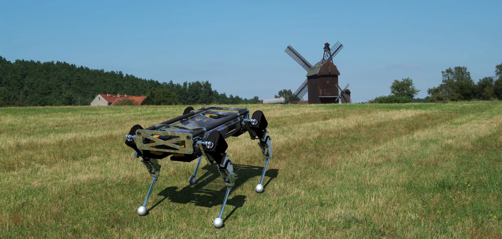
3D preview converted from github.com/popi-mkx3/popi_project at d5ef99c, under BSD-3-Clause. View the original files from GitHub (7.4 MB) (opens in a new tab)
What it can do
Written by Robotheca from the project's documents.
- POPI is an open-source quadruped robot with 12 actuators, three per leg, weighing about 71 kg and about 1 meter long.
- The pitching hip and knee actuators let the robot move linearly, while the rolling hip actuator lets it turn and keep balance.
- The software is based on ROS and C++, and can also drive a virtual POPI for developing walking trajectories.
- The power comes from two 24V supplies outside the robot, connected through an umbilical cable.
Bill of materials
This repository has no parts list Robotheca can read yet.
Build guide
The guide appears here as you scroll.
Guide by @popi-mkx3 (README.md), under BSD-3-Clause.
More guides
Wiring and electronics
Notes written by Robotheca from the project's documents.
Main parts
- Raspberry Pi 3B+ main onboard computer that hosts the controllers and computes each joint set point.
- Two BeagleBone Black computers, each managing the sensors and actuators of two legs.
- Potentiometers measure the knee and hip rolling joint positions.
- A custom encoder and control PCB measure the hip pitching joints.
- A custom current sensor PCB measures motor consumption.
- A power supply board supplied by two 24V power supplies located outside the robot.
Connections
- The Raspberry Pi communicates with the two BeagleBone Black computers, one for the right legs and one for the left legs.
- Capacitors of about 100nF sit just before the BeagleBone to filter the potentiometer analog signals.
- The robot is powered through an umbilical cable from the external 24V supplies and power supply board.
- Wiring diagrams and a pin planning spreadsheet describe the connections, though they are in French.