OnesArm
A modular serial robotic arm built from interchangeable joint, link and end-effector modules for multi-scenario tasks.
- Robot arm
- Open source
- 3D printable
Suggested by Robotheca, created by @Robusr (opens in a new tab), from github.com/Robusr/OnesArm (opens in a new tab). Pinned to commit f5d0613 (opens in a new tab).
- Hardware license
- CC-BY-4.0 (opens in a new tab)
- Software license
- MIT (opens in a new tab)
- Commercial use
- Allowed
This repository contains executable files that Robotheca doesn't check. Only run them if you trust the creator.
Photo and 3D model
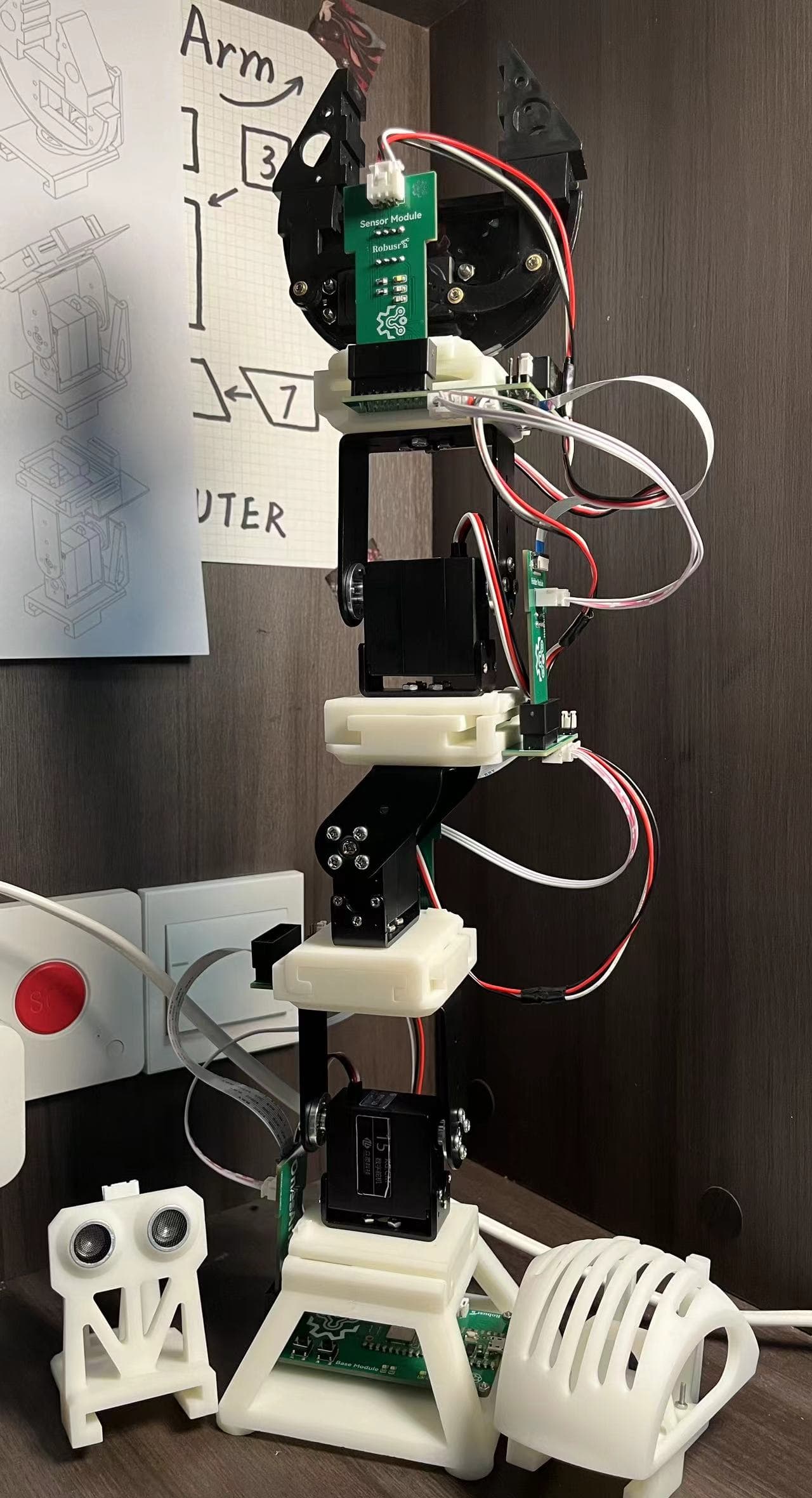
3D preview converted from github.com/Robusr/OnesArm at f5d0613, under CC-BY-4.0. View the original files from GitHub (1.2 MB) (opens in a new tab)
- Degrees of freedom
- 4
- Power
- 350 W
- Reach
- 450 mm
What it can do
Written by Robotheca from the project's documents.
- Serial modular robotic arm built from interchangeable joint, link and end-effector modules joined by T/N mortise-and-tenon interfaces.
- V2 is the current platform, with 24 joint layouts from three modules and two perpendicular channels.
- V2 analysed configuration AyCxBy-D is a 4-DOF chain with DH parameters given in the report.
- V2 end effectors include a parallel gripper, HC-SR04 ultrasonic probe, MQ gas sensor and pen module.
- V1 reference build is servo-driven, with a Raspberry Pi Pico W controller and five module boards.
Bill of materials
46 parts46 of 46 parts shown
| # | Component | Quantity | Est. price | Supplier |
|---|---|---|---|---|
| 1 | X-X long link | 4 | – | – |
| 2 | X-Y long link | 4 | – | – |
| 3 | Short link | 4 | – | – |
| 4 | Base plate | 2 | – | – |
| 5 | Motor support | 6 | – | – |
| 6 | Flange connecting plate | 6 | – | – |
| 7 | Base support | 1 | – | – |
| 8 | XX long carbon tube | 2 | – | – |
| 9 | XY long carbon tube | 2 | – | – |
| 10 | Short carbon tube | 2 | – | – |
| 11 | Base carbon tube | 1 | – | – |
| 12 | Joint bottom | 3 | – | – |
| 13 | Joint top | 3 | – | – |
| 14 | Fixture base | 1 | – | – |
| 15 | Base | 1 | – | – |
| 16 | Gas sensor housing | 1 | – | – |
| 17 | Gas sensor base | 2 | – | – |
| 18 | Ultrasonic module base | 1 | – | – |
| 19 | Print batch 1 | 1 | – | – |
| 20 | Reprint batch | 1 | – | – |
| 21 | 45 degree joint module | 1 | – | – |
| 22 | 90 degree joint module | 2 | – | – |
| 23 | Digital servo | 3 | – | – |
| 24 | Stepper motor | 3 | – | – |
| 25 | Planetary gearbox | 3 | – | – |
| 26 | Magnetic encoder closed-loop controller | 3 | – | – |
| 27 | Raspberry Pi Pico W | 1 | – | – |
| 28 | Base PCB | 1 | – | – |
| 29 | Joint A / Joint B PCB | 2 | – | – |
| 30 | Holder / Sensor PCB | 1 | – | – |
| 31 | Expand Controller PCB | 1 | – | – |
| 32 | STM32F103C8T6 CAN module | 3 | – | – |
| 33 | STM32F407ZGT6 CAN controller | 1 | – | – |
| 34 | DC power supply | 1 | – | – |
| 35 | Aluminium profile frame | 1 | – | – |
| 36 | Test positioning plate | 3 | – | – |
| 37 | Parallel gripper | 1 | – | – |
| 38 | Ultrasonic module | 1 | – | – |
| 39 | Gas sensor module | 1 | – | – |
| 40 | Pen module | 1 | – | – |
| 41 | M3 / M5 screws and nuts | – | – | – |
| 42 | Module interconnect | – | – | – |
| 43 | Internal module wiring | – | – | – |
| 44 | OnesArm Controller board | 1 | – | – |
| 45 | OnesArm Monitor board | 1 | – | – |
| 46 | v1 module board set | 1 | – | – |
46 of 46 needed parts have no price in the source, so there is no parts total. Read from BOM/onesarm_bom.csv at the pinned commit.
Build guide
The creator's steps, each with its instructions.
- 1Fabricate the aluminium and carbon structure
- 2Print the 9400A joint housings
- 3Fabricate the electronics from Gerber files
- 4Assemble the 4040 platform and power supply
- 5Configure the STM32 CAN joint modules
- 6Run the kinematics verification scripts
The guide appears here as you scroll.
Guide by @Robusr (README.md), under CC-BY-4.0 (hardware) and MIT (software).
More guides
Wiring and electronics
Notes written by Robotheca from the project's documents.
Main parts
- STM32F407ZGT6 CAN bus controller in v2.
- STM32F103C8T6 CAN module in each v2 joint.
- 42BYGH47 stepper motors with FLE-42-20 planetary reducers (1:20) and magnetic encoder closed-loop control in v2.
- TJA1050 CAN transceivers and an LM2596-5.0 logic regulator in v2.
- 350 W DC supply with XT60 input in v2.
- Raspberry Pi Pico W (RP2040, Wi-Fi) controller in v1.
- 15 kgf·cm PWM digital servos in v1, powered from a 5–9 V rail.
- V1 module boards: Base, Joint A, Joint B, Holder/Sensor and Expand Controller.
Connections
- V2 joints are connected on a CAN bus in a daisy chain.
- V2 supply enters through XT60, with 5 V logic derived from the LM2596 regulator.
- V1 modules are interconnected with a 16P 2.54 mm gold-finger connector.
- V1 joint boards provide 3 PWM outputs, 5 LEDs and a servo signal selector per joint.
- The gold-finger connector is not reverse-polarity protected, according to the assembly notes.
Cables and connectors
From the parts list.
- Internal module wiring
Schematics, boards and diagrams
- electronics/output/gerber/controller_monitor/Gerber_OnesArm_Controller_PCB_OnesArm_Controller_2024-07-20.zipGerber (PCB manufacturing)
- electronics/output/gerber/controller_monitor/Gerber_OnesArm_Monitor_PCB_OnesArm_Monitor_2024-07-20.zipGerber (PCB manufacturing)
- electronics/output/gerber/v1_module_boards/Gerber_OnesArm_Base_PCB_OnesArm_Base_2024-02-17.zipGerber (PCB manufacturing)
- electronics/output/gerber/v1_module_boards/Gerber_OnesArm_ExpandController_v1_PCB_OnesArm_ExpandController_v1_2024-03-17.zipGerber (PCB manufacturing)
- electronics/output/gerber/v1_module_boards/Gerber_OnesArm_HolderPort_PCB_OnesArm_HolderPort_2024-02-17.zipGerber (PCB manufacturing)
- electronics/output/gerber/v1_module_boards/Gerber_OnesArm_JointPort_PCB_OnesArm_JointPort_2024-02-17.zipGerber (PCB manufacturing)
- electronics/output/gerber/v1_module_boards/Gerber_OnesArm_SensorsPort_PCB_OnesArm_SensorsPort_2024-02-17.zipGerber (PCB manufacturing)