Project files
2 KB
Machine-translated by Robotheca from the original in Japanese (opens in a new tab). License: CC-BY-SA-4.0 (opens in a new tab).
Completed Photos
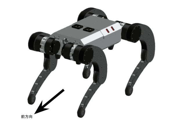
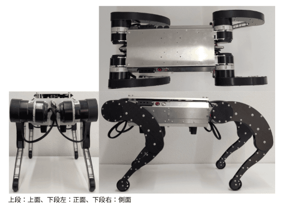
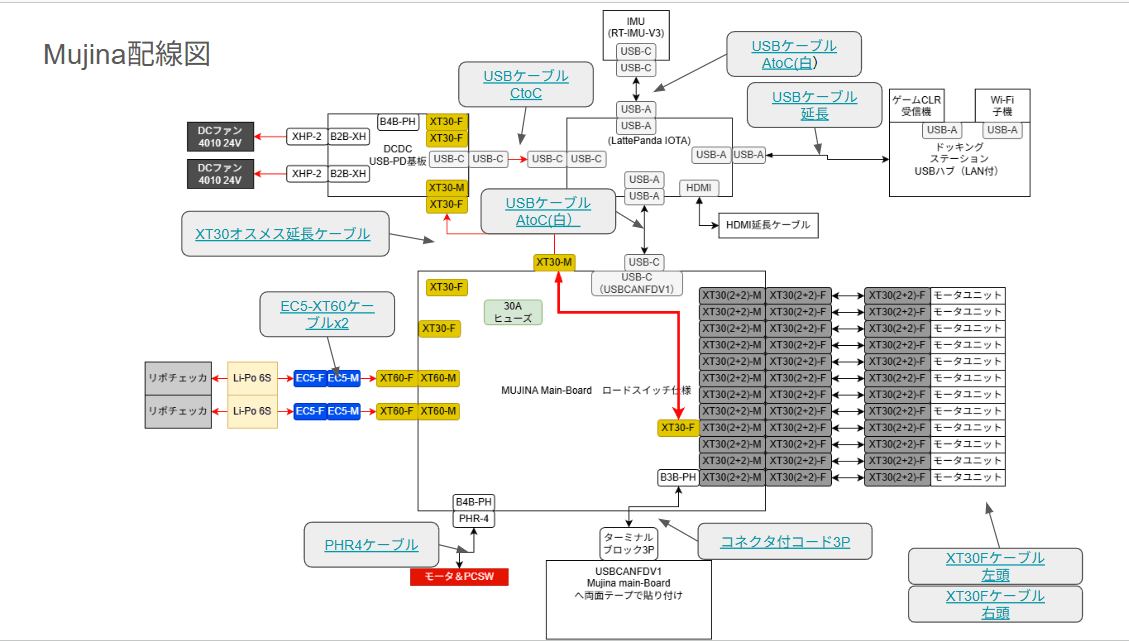
Wiring Diagram
Notes on Assembly
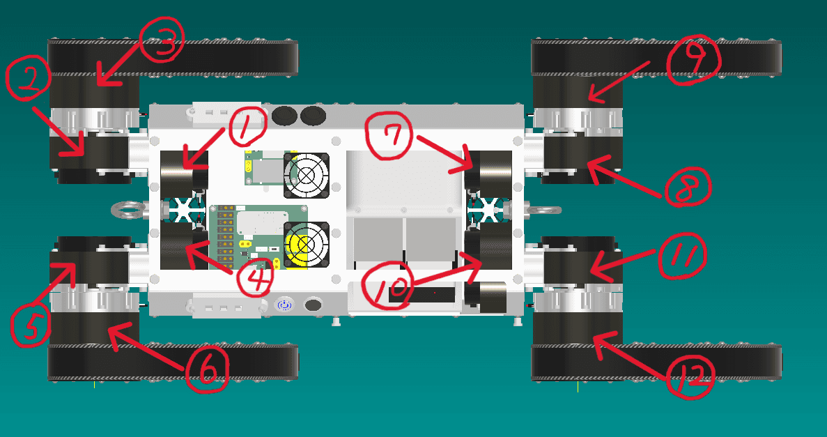
Motor ID Writing and Firmware Update
Mujina's motor ID assignments are shown in the image.
For writing IDs and updating firmware, see 「motor_tool.md」.
Writing Firmware
The USB-output 9-axis IMU sensor module V3 (opens in a new tab) and the 「WeAct」USB-CANFD interface (opens in a new tab) require firmware to be written. See 「firmware.md」, and after writing, install them into the robot body.
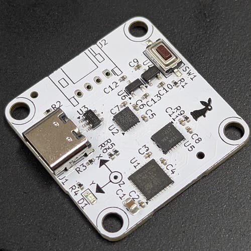

Preparing the LATTEPANDA IOTA
Mujina has a built-in 「LATTEPANDA」 (opens in a new tab). Before assembly, refer to the README of Mujina_ros (opens in a new tab) and set up the PC.
- Setting AUTO Power ON
- By default, the LATTEPANDA is powered on with the switch on the side of the unit. Since it is built into the body, you need to configure it to start automatically when power is applied. The official "Auto Power-On" documentation is here (opens in a new tab).
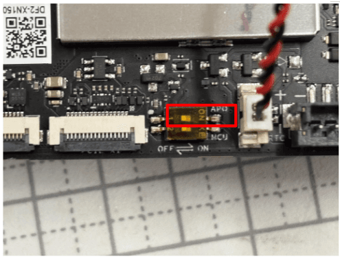
Turning on the switch outlined in red in the photo starts the PC at the same time power is applied.
For installation into Mujina, see lattepanda.md.
Wiring
For wiring inside the Mujina body, motor cables, and similar connections, see cable.md.
※Insulate the XT30 (2+2) connectors of any motors that do not have motor cables connected.

Files by @rt-net, at commit 6eaa30f, read from GitHub in your browser. Hardware license: CC-BY-SA-4.0; software license: CC-BY-SA-4.0. Robotheca doesn't review code: read it before running it.