Mini-Arm
A miniature 6DOF 3D-printed open-source robot arm controlled from a Raspberry Pi Pico running CircuitPython, with an internal IK solver and USB, serial and TCP/IP control.
- Robot arm
- Open source
- micropython
- 3D model (URDF)
- 3D printable
Suggested by Robotheca, created by @Jshulgach (opens in a new tab), from github.com/Jshulgach/Mini-Arm (opens in a new tab). Pinned to commit 666bbb4 (opens in a new tab).
- Hardware license
- MPL-2.0 (opens in a new tab)
- Software license
- MPL-2.0 (opens in a new tab)
- Commercial use
- Allowed
This repository contains executable files that Robotheca doesn't check. Only run them if you trust the creator.
Which files (1 script, 4 firmware images)
- docs/make.bat (opens in a new tab)
- firmware/circuitpython/Pico_CircuitPython-9.2.7/adafruit-circuitpython-raspberry_pi_pico-en_US-9.2.7.uf2 (opens in a new tab)
- firmware/circuitpython/Pico2W_CircuitPython-9.2.4/adafruit-circuitpython-raspberry_pi_pico2_w-en_US-9.2.4.uf2 (opens in a new tab)
- firmware/circuitpython/PicoW_CircuitPython-8.2.7/adafruit-circuitpython-raspberry_pi_pico_w-en_US-8.2.7.uf2 (opens in a new tab)
- firmware/circuitpython/PicoW_CircuitPython-8.2.7/flash_nuke.uf2 (opens in a new tab)
Photo and 3D model
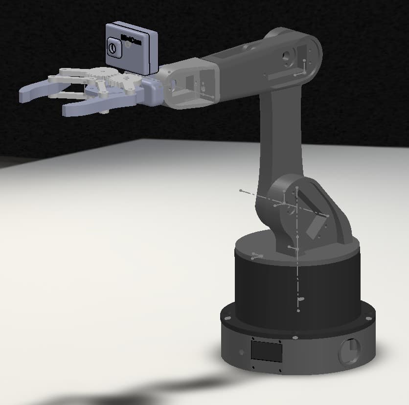
3D preview converted from github.com/Jshulgach/Mini-Arm at 666bbb4, under MPL-2.0. View the original files from GitHub (1.3 MB) (opens in a new tab)
4 mesh files named in the URDF are not in the repository, so those parts are not shown.
- Degrees of freedom
- 6
- Weight
- 0.3 kg
What it can do
Written by Robotheca from the project's documents.
- Controls a miniature 6DOF 3D-printed robot arm over USB serial using a Python client library (MiniArmClient).
- Moves the end effector to Cartesian XYZ poses, with an internal inverse kinematics solver running on the microcontroller.
- Supports joint and delta pose commands, home position, gripper open/close, LED color, and predefined trajectories such as circle.
- Can be teleoperated with an Xbox controller in real time, with gripper control via triggers.
- Reads force sensing resistors (FSRs), and includes face detection and camera streaming demos and tests.
- Can be visualized in RViz2 via the included ROS2 packages and driven through MoveIt2 configuration.
Bill of materials
This repository has no parts list Robotheca can read yet.
Build guide
The creator's steps, each with its instructions.
- 1Choose Pico firmware
- 2Flash the firmware
- 3Copy the firmware files
- 4Building the arm
- 5Electrical wiring
The guide appears here as you scroll.
Guide by @Jshulgach (README.md), under MPL-2.0.
More guides
Wiring and electronics
Notes written by Robotheca from the project's documents.
Main parts
- Raspberry Pi Pico 2 microcontroller (a Pico variant is also supported) running CircuitPython.
- Multiple servo motors driving the arm joints and gripper.
- Force sensing resistors (FSRs) for sensing.
- RGB LED used as a status indicator.
- Camera module, such as an ESP32-CAM, used in some demos and tests.
- USB connection to the host computer.
Connections
- Wiring diagram is provided as an image in the repository at assets/wiring.PNG.
- The Pico communicates with the host over USB serial at a default baudrate of 115200 in the client, while examples mention 9600.
- Servos and other peripherals connect to the Pico as shown in the wiring diagram; the text does not describe pin assignments.
