M5Stack Walk-chan
A small bipedal walking robot controlled by an M5Stack board, with a sliding battery that shifts its balance between legs.
- Other
- Open source
- arduino
- 3D printable
Suggested by Robotheca, created by @tomorrow56 (opens in a new tab), from github.com/tomorrow56/M5Stack_Walk-chan (opens in a new tab). Pinned to commit 0de1575 (opens in a new tab).
- Hardware license
- MIT (opens in a new tab)
- Software license
- MIT (opens in a new tab)
- Commercial use
- Allowed
Photo and 3D model
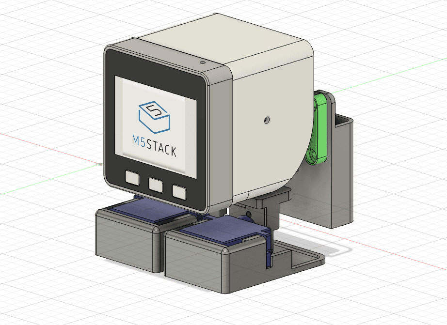
3D preview converted from github.com/tomorrow56/M5Stack_Walk-chan at 0de1575, under MIT. View the original files from GitHub (10.6 MB) (opens in a new tab)
What it can do
Written by Robotheca from the project's documents.
- Bipedal walking robot built around an M5Stack controller board, sized after Otto DIY style small walkers.
- Walks in alternating left and right steps: shifts a ballast battery sideways, tilts the ankles, swings legs forward and back.
- Battery ballast moves on a rack-and-pinion mechanism to keep the center of gravity over the supporting leg.
- Shows an avatar (eyes) on the M5Stack LCD that is synchronized with walking.
- Shows battery and charging status; a charging mode lets the user adjust the home position and switch to the walk demo with button B.
Bill of materials
This repository has no parts list Robotheca can read yet.
Build guide
The creator's steps, each with its instructions.
- 1Print the 3D parts from the STL files in 3Ddata/stl/
- 2Assemble the servos, gears and battery holder using the STEP assembly as referen
- 3Manufacture and solder the servo driver PCB from the Gerber files
- 4Connect the M5Stack and the servos to the PCB
- 5Build and flash the WalkTest sketch with Arduino IDE or PlatformIO
- 6Power on and check the walking motion, adjusting the center and range constants
The guide appears here as you scroll.
Guide by @tomorrow56 (README.md), under MIT. The English translation is by Robotheca, shared under the same license.
Wiring and electronics
Notes written by Robotheca from the project's documents.
Main parts
- M5Stack controller board (Basic, Gray, Fire and similar).
- Five SG90-compatible servo motors: two ankles, two legs, one ballast drive.
- Custom PCB that converts the M5Stack M-Bus into direct PWM servo connectors, without a servo driver IC.
- Grove-compatible connector for external sensor expansion.
- Lithium-ion battery (NP-40 type recommended) as the ballast and power source; M5Stack internal power management IC IP5306.
Connections
- Servos are driven directly from M5Stack GPIO pins using LEDC PWM channels: FootR on GPIO 2, FootL on GPIO 12, LegR on GPIO 0, LegL on GPIO 15, Ballast on GPIO 13.
- The custom PCB plugs into the M5Stack M-Bus and breaks out one PWM connector per servo.
- Servo power is selected by solder jumper: from the PCB connector or from the M-Bus 5V.
- A 2-pin header connects a 5V servo supply and the M5Stack lithium-ion battery.
- A physical switch on the side of the board turns the M5Stack on and off.
