Hexapod
A family of 18-DOF, 3D-printed hexapod walking robots powered by an ESP32, controlled over WiFi or live pose streaming.
- Other
- Open source
- arduino
- 3D printable
Suggested by Robotheca, created by @rookidroid (opens in a new tab), from github.com/rookidroid/hexapod (opens in a new tab). Pinned to commit 625d150 (opens in a new tab).
- Hardware license
- GPL-3.0-only (opens in a new tab)
- Software license
- GPL-3.0-only (opens in a new tab)
- Commercial use
- Allowed
Photo and 3D model
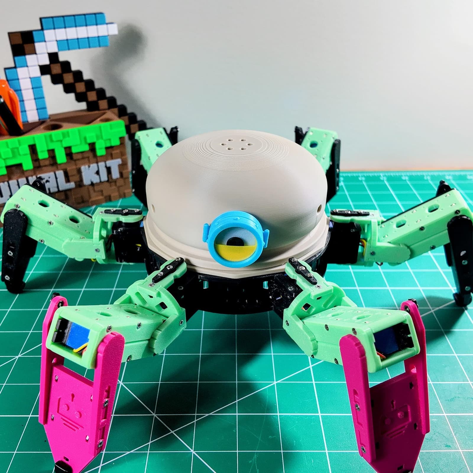
3D preview converted from github.com/rookidroid/hexapod at 625d150, under GPL-3.0-only. View the original files from GitHub (28.2 MB) (opens in a new tab)
- Degrees of freedom
- 18
What it can do
Written by Robotheca from the project's documents.
- Walks in 18 directions and gaits, including forward, backward, sideways at 45/90/135 degrees, turns in place, climbing and body rotation
- Supports real-time streaming of all 18 joint positions at 50 Hz with a 1 second failsafe
- Runs a stand-up boot sequence when a client joins its WiFi access point
- Supports over-the-air firmware updates over WiFi
Bill of materials
This repository has no parts list Robotheca can read yet.
Build guide
The guide appears here as you scroll.
Guide by @rookidroid (README.md), under GPL-3.0-only.
More guides
Wiring and electronics
Notes written by Robotheca from the project's documents.
Main parts
- ESP32 controller board with dual PCA9685 PWM drivers
- 18 x 25 kg digital servos, 180 degree travel, rated for 8.4 V
- 4 x 18650 Li-ion cells in 2S2P holder, 7.4 V nominal
- SPST toggle power switch
Connections
- Dual PCA9685 drivers are on I2C addresses 0x40 (left legs) and 0x41 (right legs)
- Enable pins are GPIO 19 for left legs and GPIO 26 for right legs
- Servo pin mappings are defined in the firmware and can be changed for custom wiring
- Servos are powered directly from the batteries; the controller board is pre-assembled and needs no soldering


