HEX-B12 Hexapod
A custom-designed hexapod robot with MG996R servos, themed after the robot B-12 from the video game Stray, controlled by a wireless remote.
- Other
- Open source
- arduino
- 3D printable
Suggested by Robotheca, created by @Josh4minee (opens in a new tab), from github.com/Josh4minee/HEX-B12.V1 (opens in a new tab). Pinned to commit dd9b695 (opens in a new tab).
- Hardware license
- MIT (opens in a new tab)
- Software license
- MIT (opens in a new tab)
- Commercial use
- Allowed
Photo and 3D model
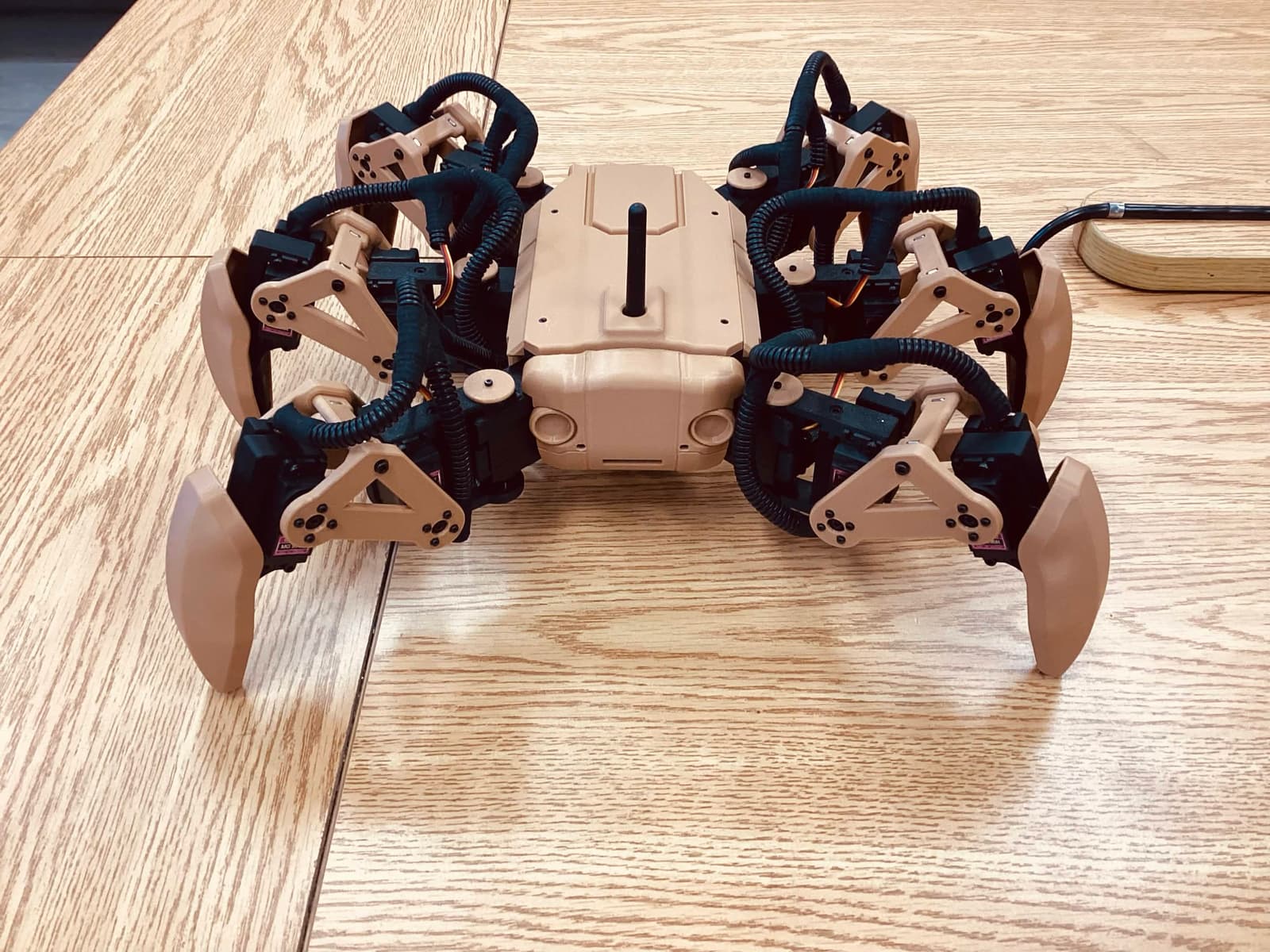
3D preview converted from github.com/Josh4minee/HEX-B12.V1 at dd9b695, under MIT. View the original files from GitHub (21.0 MB) (opens in a new tab)
What it can do
Written by Robotheca from the project's documents.
- Hexapod walking robot with six legs using MG996R servos, inspired by the B-12 robot from Stray
- Walking gaits selectable from the remote: tripod (button 1), ripple (button 2), and an Easter egg gait (button 3)
- Normal walking mode turns the body to follow the joystick direction
- Crab mode moves in joystick directions without turning the body
- Body control mode adjusts planar offset, XY rotation offset, and Z rotation of the body
- Animation mode plays three selectable animations using the remote's three buttons
- Global height offset controlled by the lower knob on the remote
- Start animation begins about 10 seconds after the battery is plugged in
Bill of materials
This repository has no parts list Robotheca can read yet.
Build guide
The creator's steps, each with its instructions.
- 1Set all servos to 90 degrees before assembly
- 2Print the STL parts with the recommended settings
- 3Assemble the coxa, femur and tibia parts
- 4Assemble the legs, keeping 3 legs flipped
- 5Assemble the mid frame and attach the legs
- 6Mount the electronics
- 7Wire the hexapod according to the wiring diagram
- 8Order and solder the remote PCB from the gerber files
- 9Assemble the remote
The guide appears here as you scroll.
Guide by @Josh4minee (README.md), under MIT.
Wiring and electronics
Notes written by Robotheca from the project's documents.
Main parts
- Arduino Nano as the main controller
- Adafruit PCA9685 16-channel PWM servo driver
- MG996R servos (18 total, one per leg joint)
- NRF24L01+PA+LNA wireless radio modules on both robot and remote
- Three UBECs converting 7V to 5V
- 2S LiPo battery, 5200mAh
- 10A manual reset fuse
- Double relay module, used to delay servo power about 5 seconds after battery connection
- Custom remote PCB with three buttons, two knobs, and a joystick
Connections
- Battery feeds the fuse, then the UBECs step 7V down to 5V for the electronics
- Relay switches power to the servos about 5 seconds after the battery is plugged in
- PCA9685 servo driver connects the Arduino Nano to the servos
- NRF24L01+ modules are powered from their breakout power boards on the remote PCB
- Detailed pin connections are shown in the wiring diagram images in the pictures folder and the KiCad schematic


