Project files
- images10 files
- mechanics68 files
- program7 files
- .gitignore1 KB
- A_Compact_and_Lightweight_Rigid-Tendon_Combined_Exoskeleton_for_Hand_Rehabilitation.pdf32.3 MB
- LICENSE1 KB
- README.md17 KB
README.md
Machine-translated by Robotheca from the original in Chinese (opens in a new tab). License: MIT (opens in a new tab).
hand_exoskeleton Low-Cost Hand Exoskeleton
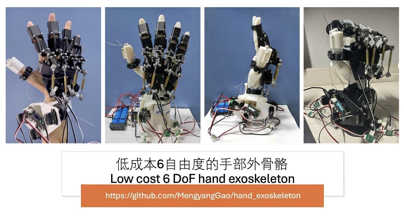
A low-cost 6DoF hand exoskeleton using linkage and tendon mechanism under ESP32.
A low-cost 6-degree-of-freedom hand exoskeleton priced at around 500 RMB, using linkage-driven mechanisms for the four fingers and a tendon-driven mechanism to simulate muscle-tendon action for the thumb. The main controller is an ESP32, powered by seven SC09 bus servos, capable of supporting loads greater than 20N.
Open source: https://github.com/MengyangGao/hand_exoskeleton (opens in a new tab)
Paper: A Compact and Lightweight Rigid-Tendon Combined Exoskeleton for Hand Rehabilitation
News Update Log
2026-06-03: Paper uploaded. Documentation updated.
2024-11-16: README improved, details added. DIY battery holder illustrated guide completed.
2024-11-24: 3D printing files uploaded, README updated.
2025-05-06: Thumb details added
3. Assembly (TODO)
Assembly of the four fingers is relatively simple and you can refer to the netizen's reproduction video: Reproduction Video: "Assembling a Mechanical Hand as a Mechanical Novice – Part 1: Materials" (opens in a new tab). The thumb's wire-driven mechanism requires a wire to pass horizontally through the four-finger linkage structure to provide pulling force from that direction.
Materials
- Mechanical components
- SC09 bus servos * 7
- M3 ball bearings * 8
- Assorted M2 and M3 screws and nuts, hex screwdriver, Phillips screwdriver
- Hex copper pillars *4 (inner diameter 3.2 mm, length 20–38 mm, to match ball bearings and software angle settings)
- Wire 0.8 mm
- 3D printing (this project uses PLA filament and the Bambu Studio (opens in a new tab) slicing software)
- Electronics
- Main controller: ESP32 microcontroller * 1
- Signal wires and wiring board (if you purchase materials from the recommended vendor, these two items are included in each servo package)
- Power supply: Refer to the M5Stack ESP32 documentation (opens in a new tab) for the ESP32 board’s operating voltage of 6–12 V with a 5.5×2.1 mm DC jack. Refer to the M5Stack SC09 Servo documentation (opens in a new tab) for the SC09 servo’s operating voltage of 4.8–8.4 V. Therefore, you will need:
- A 6–12 V power supply with a 5521 DC jack; since the servos are connected in a bus, the supply voltage should increase with the number of servos.
- Or two 18650 batteries (3.7 V) in series + 5521 DC adapter + battery holder (a tutorial for making the battery holder is complete; see the image below. Note: for insulation and safety you can add electrical tape or heat-shrink tubing, and to avoid repeated plugging you can add a power switch. Safety first! Beginners are advised to choose the first option and simply buy a suitable adapter power supply.)

- Assorted wires and solder
- Soldering iron
- (Optional) Heat gun, heat-shrink tubing, power switch
- Software
- Development: VS Code for iterative coding, Arduino IDE for flashing
- Device: A computer capable of uploading programs; tested on macOS and Windows. The ESP32 uses a Type-C programming port
- Usage: Any Wi-Fi-enabled device with a graphical interface
Mechanics Mechanics Introduction
 |  |
|---|
Basic Information
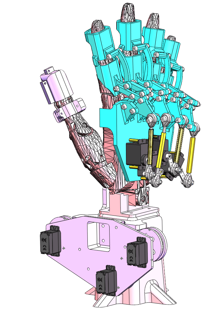
Linkage combined with wire-driven control.
Weight: Thumb exoskeleton 174g, four-finger exoskeleton 226g, total weight approximately 400g. (Including servos and various parts and materials, excluding hand model and power supply)
Dimensions: 150x150x310mm
Load capacity: Total pulling force of four fingers >20N.

The parts that fit the hand are designed with rounded corners for good comfort.
The four fingers are easy to wear, simply slip them onto the hand. The thumb requires a ring and wire pulling, making it a bit more complex.
Four-Finger Linkage

The transmission part converts horizontal motion into vertical motion of the fingers using a crank-linkage and eyeball bearings, while limiting the stroke of the rocker to ensure safety. Each finger in the execution part employs an eight-link system. Considering that there is no space to wear an exoskeleton on either side of the MCP joint, two sets of parallelogram four-bar linkages are used to extend the joint. The PIP joint is designed with a four-bar linkage to accurately control the bending degree, and further ensures that the finger does not bend in the opposite direction through interference between screws.
Thumb — Tendon-Driven
The thumb uses three servos to achieve two degrees of freedom with a compact, flexible, over-driven tendon control.
 |  |
|---|
Servo 1 and Servo 3 control one axis of freedom, while Servo 2 controls the freedom of the other axis perpendicular to the horizontal plane.
Program Introduction
Basic Information
Single servo control: st.WritePos(2, 450, 0, 400); The first parameter 2 indicates the servo ID is 2, the second parameter 450 indicates the target angle is 450, and the fourth parameter 400 indicates the rotation speed is 400. The third parameter can be ignored.
For controlling multiple servos simultaneously, store the servo IDs, positions, and speeds in corresponding arrays, then use st.SyncWritePos(ID, 7, Position, 0, Speed); where the parameters are servo ID, number of servos, angle, the fourth parameter can be ignored, and speed.
To control multiple servos, you need to define byte ID[], u16 Position[], u16 Speed[] in STSCTRL.h, with the number of elements filled in the square brackets.
Important reference documents:
ServoDriver.ino
ServoDriver.ino is the main program, and void loop() is the main function. Any program written here will be automatically executed in a loop as soon as the main controller is powered on.
The following lines in void setup() are used to initialize the servos, match the servo IDs, and calculate the variables in the computer:
  ID[0] = 1; //Match servo ID. The thumb is 1, 2, 3, and the other four fingers are 4, 5, 6, 7. For each servo, you need to modify the corresponding entries in STSCTRL.h for byte ID[], Position[], and Speed[].
  ID[1] = 2;
  ID[2] = 3;
  ID[3] = 4;
  ID[4] = 5;
  ID[5] = 6;
  ID[6] = 7;
As long as it is powered, you can find the ESP32's local area network hotspot in the Wi-Fi list. After connecting, you can access the web debugging interface by visiting 192.168.4.1 in your browser (provided that the Wi-Fi-related program has not been commented out or deleted).
This program adds serial debugging-related routines in loop to facilitate development and testing. The usage method is as follows: (After setting up the development board environment, baud rate, etc.) Connect the ESP32 to the computer via Type-C, and open the serial monitor in the upper right corner of Arduino. There are two types of input:
-
Single servo rotation command in the format
[ID] [Position] [Speed], which requires spaces. -
Action plan in the format
[caseNumber].
CONNECT.h
In the activeCtrl switch case here, add the desired action plan. For example, case 23 is the predefined Open Hand function.
case 23: // Open Hand
        openHand();
        moveThumbSameTime(1000, 100, 0, setSpeed);
        break;
You can directly use methods like WritePos introduced earlier to write the desired rotation plan. The two sub-functions here are defined and encapsulated outside. Refer to CONNECT.h to view their definitions.
Here, you can create many action plans and work related to software development. If you're interested, you can directly download the official M5Stack files and see the differences between them and this project.
WEBPAGE.h
WEBPAGE.h is the development of the web front-end interface. Essentially, it is HTML+JavaScript+CSS.
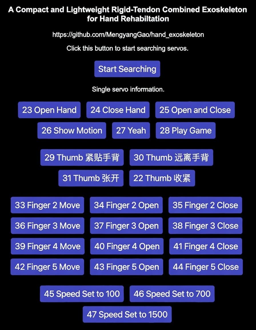
To develop new features for the web front-end, add a new case in the active Control function in CONNECT.h, then call the toggleCheckbox function in WEBPAGE.h. (It is recommended to start from case 30 and avoid overlapping with the official cases.)
For example, see the following, which adds a button called "23 Open Hand". Clicking it will trigger the case corresponding to the second parameter in the toggleCheckbox function. What is case 23? You need to write it yourself. In this project, case 23 corresponds to Open Hand.
<label align="center"><button class="button" onclick="toggleCheckbox(1, 23, 0, 0);">23 Open Hand</button></label>
Here, you can do a lot of web front-end related work. If you are interested, you can directly pull down the official Waveshare files and see what differences there are with this project.
Development Log
-
v0.2 Tested suitable rotation angles for the index and thumb servo motors (No. 2), and placed them in the main loop function.
-
v0.3 Added Move, Open, and Close buttons and action schemes for the four fingers on the web frontend. Re-adjusted the rotation parameters of the little finger (servo motor No. 7) based on the testing of the servo arms and device to avoid interference. Changed the Wi-Fi name to
ESP32_KevinStarkand the password to88888888. -
v0.4 Added thumb control scheme: first
relaxThumbto loosen the wires of servos No. 1 and No. 3, then move them. Encapsulated many functions to improve maintainability and added many action schemes. -
v0.5 Optimized code structure and encapsulated functions. Stabilized the thumb by opening it first before tightening. Added action schemes such as coordinated movement of the four fingers and thumb, and "rock-paper-scissors" game. Organized the web frontend layout. Added a serial debugging program in
ServoDriver.inothat can receive single-servo rotation commands in the format"[ID] [Position] [Speed]"and action schemes in the format"[caseNumber]". -
v1.0 Added three speed options: 100, 700, and 1500, corresponding to cases 45, 46, and 47, which only change the running speed of the four fingers. Simplified the frontend interface.
Cost
To replicate this project, you will need at least the following:
-
SC09 Servo Motor – ¥47 each, 7 required Weixun SC09 Serial Bus Servo Motor 300° Metal Gear Servo Motor Dual Mode Switching (opens in a new tab)
-
ESP32 Development Board – ¥80 each, 1 required Weixun ESP32 Servo Driver Expansion Board Wi-Fi Remote Control Bluetooth Communication Supports 253 Servos (opens in a new tab)
-
Spherical Plain Bearing – ¥1.9 each, 8 required Cylinder Eye Joint Bearing Radial Self-aligning Rod End Ball Head SI Internal Thread SA External Thread Connecting Rod Tie Rod (opens in a new tab)
-
Wire – ¥2.89 per 10 m roll 304 Stainless Steel Wire Rope Clothesline Shade Net Plastic-Coated Fine Soft Small Plastic-Coated Wire Rope 0.8 mm (opens in a new tab)
Total cost: approximately ¥427.09.
Battery + soldering supplies: about ¥30. 3D printing (only for the final exoskeleton version, excluding hands and iterations; priced at ¥0.2/g PLA): about ¥30.
Additional costs include mechanical and welding consumables, tools, and shipping.
In short, if you already have welding and machining tools on hand, you can complete this project for around ¥500.
Summary and Future Plan
This project offers a low-cost 6-DOF hand exoskeleton solution, with the four fingers using linkage transmission and the thumb using cable drive.
Due to cost considerations, the motion accuracy of the finished product is average—it can specify angles but cannot achieve precision. Additionally, there are no force feedback, sensing, or other functions.
Relatively mature solutions already exist in various subfields. Therefore, integrating them is not difficult (though it would no longer be this project). Servo motor and linkage schemes have limitations in precision and degrees of freedom (as noted in the comment from 2024-11-16). If conditions permit, higher-precision drive solutions such as stepper motors or brushless DC motors will be chosen.
Looking ahead, one major direction this project aims to explore is dexterous hands.
- TODO:
DIY battery holder illustrated guide (completed)Organize and upload .3mf files (completed)- Organize and upload assembly details
- When using a web frontend, clicking once may trigger three actions. The reason is unclear—could it be multiple event listeners for the previous window? For safety, it is recommended to use serial port control until the issue is identified and resolved.
- Potential development directions:
- Master-slave teaching (ESP-NOW communication, mechanical structure optimization to reduce dead zones)
- Camera-based gesture recognition (match case already implemented; pending organization and open-sourcing. Further research needed for precise follow-up)
- Optimization of human-machine interaction, such as voice recognition input (STT), voice speaker modules, web frontend beautification (CSS), and adding user startup guidance steps
- Force feedback and soft contact grasping
- Motion planning using large language models (LLM+RAG)
- Reinforcement learning for grasping training. Research on generalization of dexterous hand grasping. Research on self-supervised learning for dexterous hand data generation.
Acknowledgements
Thanks to Khlann (opens in a new tab) and cyatar (opens in a new tab) for their advice in the embedded field.
Thanks to lvWei for guiding the soldering and sharing tips.
Thanks to the RobotIC Robotics Laboratory for providing some of the materials and tools needed for the production process.
The hand model comes from teaching assistants; if you know the original source, please let us know.
References
- Marcin Bonikowski, Mikulás Hajduk, Lucia Koukolova, Wojciech J. Klimasara, Patrycja Mrozek, and Zbigniew Pilat. New trends in the use of robotic devices in motor rehabilitation of upper limbs. In Automation, 2016.
- Anirban Chowdhury, Shyam Sunder Nishad, Yogesh Kumar Meena, Ashish Dutta, and Girijesh Prasad. Hand-exoskeleton assisted progressive neurorehabilitation using impedance adaptation based challenge level adjustment method. IEEE Transactions on Haptics, 12:128–140, 2019.
- Feiyun Xiao, Liang Gu, Wenzhang Ma, Yanhe Zhu, Zhen Zhang, and Yong Wang. Real-time motion intention recognition method with limited number of surface electromyography sensors for a 7-dof hand/wrist rehabilitation exoskeleton. Mechatronics, 79:102642, 2021.
- Phillip Tran, Seokhwan Jeong, Steven L. Wolf, and Jaydev P. Desai. Patient-specific, voice-controlled, robotic flexotendon glove-II system for spinal cord injury. IEEE Robotics and Automation Letters, 5:898–905, 2020.
- https://www.waveshare.net/wiki/Servo_Driver_with_ESP32 (opens in a new tab)
- https://www.waveshare.net/wiki/SC09_Servo (opens in a new tab)
Contributors
Mechanics:
Jiayu Chen, Jianran Zhang (opens in a new tab)
Electronics:
Mengyang Gao (opens in a new tab), Haolan Kang (opens in a new tab)
Software:
Mengyang Gao (opens in a new tab)
Report and other work:
Yi Zhu, Xuhan Lang, Mengyang Gao (opens in a new tab)
Thank you for reading about this project. You are welcome to contribute to it. If you encounter any issues, feel free to open an issue. If needed, you can contact me at gmy.kevinstark@gmail.com (opens in a new tab).
Citation
If you use this project in your research, please cite:
@article{gao2024hand_exoskeleton,
  title={A Compact and Lightweight Rigid-Tendon Combined Exoskeleton for Hand Rehabilitation},
  author={Lang, Xuhan and Kang, Haolan and Zhu, Yi and Chen, Jiayu and Zhang, Jianran and Gao, Mengyang},
  year={2024},
  note={\url{https://github.com/MengyangGao/hand_exoskeleton}}
}
Files by @MengyangGao, at commit a5d6a1d, read from GitHub in your browser. Hardware license: MIT; software license: MIT. Robotheca doesn't review code: read it before running it.