ElectronBot
A mini desktop robot with 6 degrees of freedom, USB communication, and a display screen, inspired by WALL-E's EVE.
- Humanoid
- Open source
- 3D printable
Suggested by Robotheca, created by @peng-zhihui (opens in a new tab), from github.com/peng-zhihui/ElectronBot (opens in a new tab). Pinned to commit 8199270 (opens in a new tab).
- Hardware license
- GPL-3.0-only (opens in a new tab)
- Software license
- GPL-3.0-only (opens in a new tab)
- Commercial use
- Allowed
This repository contains executable files that Robotheca doesn't check. Only run them if you trust the creator.
Which files (71 programs or installers, 2 firmware images)
- 3.Software/_Tools/AHK-ExpansionPack/ElectronBotSDK/autoit_opencv_com455.dll (opens in a new tab)
- 3.Software/_Tools/AHK-ExpansionPack/ElectronBotSDK/concrt140d.dll (opens in a new tab)
- 3.Software/_Tools/AHK-ExpansionPack/ElectronBotSDK/ElectronBotSDK-LowLevel.dll (opens in a new tab)
- 3.Software/_Tools/AHK-ExpansionPack/ElectronBotSDK/ElectronBotSDK-Player.dll (opens in a new tab)
- 3.Software/_Tools/AHK-ExpansionPack/ElectronBotSDK/ElectronBotSDK源码/ElectronBotSDK-LowLevel/lib/USBInterface.dll (opens in a new tab)
- 3.Software/_Tools/AHK-ExpansionPack/ElectronBotSDK/ElectronBotSDK源码/ElectronBotSDK-LowLevel/src/lib/ElectronBotSDK-LowLevel.dll (opens in a new tab)
- 3.Software/_Tools/AHK-ExpansionPack/ElectronBotSDK/ElectronBotSDK源码/ElectronBotSDK-LowLevel/src/lib/USBInterface.dll (opens in a new tab)
- 3.Software/_Tools/AHK-ExpansionPack/ElectronBotSDK/ElectronBotSDK源码/ElectronBotSDK-Player/lib/ElectronBotSDK-LowLevel.dll (opens in a new tab)
- 3.Software/_Tools/AHK-ExpansionPack/ElectronBotSDK/ElectronBotSDK源码/ElectronBotSDK-Player/lib/USBInterface.dll (opens in a new tab)
- 3.Software/_Tools/AHK-ExpansionPack/ElectronBotSDK/ElectronBotSDK源码/ElectronBotSDK-Player/src/lib/ElectronBotSDK-Player.dll (opens in a new tab)
- 3.Software/_Tools/AHK-ExpansionPack/ElectronBotSDK/libusb0.dll (opens in a new tab)
- 3.Software/_Tools/AHK-ExpansionPack/ElectronBotSDK/msvcp140d.dll (opens in a new tab)
- 3.Software/_Tools/AHK-ExpansionPack/ElectronBotSDK/opencv_videoio_ffmpeg455_64.dll (opens in a new tab)
- 3.Software/_Tools/AHK-ExpansionPack/ElectronBotSDK/opencv_world455.dll (opens in a new tab)
- 3.Software/_Tools/AHK-ExpansionPack/ElectronBotSDK/ucrtbased.dll (opens in a new tab)
- 3.Software/_Tools/AHK-ExpansionPack/ElectronBotSDK/USBInterface.dll (opens in a new tab)
- 3.Software/_Tools/AHK-ExpansionPack/ElectronBotSDK/vcruntime140_1d.dll (opens in a new tab)
- 3.Software/_Tools/AHK-ExpansionPack/ElectronBotSDK/vcruntime140d.dll (opens in a new tab)
- 3.Software/_Tools/BotDriver/amd64/libusb0.dll (opens in a new tab)
- 3.Software/_Tools/BotDriver/ia64/libusb0.dll (opens in a new tab)
- and 53 more
Photo and 3D model
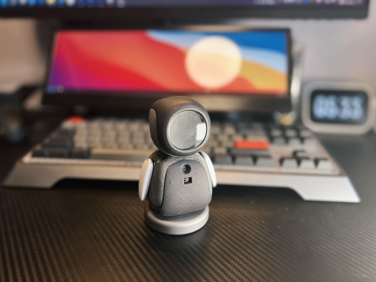
3D preview converted from github.com/peng-zhihui/ElectronBot at 8199270, under GPL-3.0-only. View the original files from GitHub (33.9 MB) (opens in a new tab)
- Degrees of freedom
- 6
What it can do
Written by Robotheca from the project's documents.
- 6 degrees of freedom arm and head movement (roll, pitch, neck, waist)
- USB communication with host computer
- Display screen on head for video and images
- Hand gesture sensing
- Voice recognition in voice version
- Camera input via USB
- Custom USB-CDC device protocol
- PID closed-loop control for servos
Bill of materials
This repository has no parts list Robotheca can read yet.
Build guide
The creator's steps, each with its instructions.
- 1Prepare 3D printed parts
- 2Assemble structural components
- 3Install bearings and special screws
- 4Prepare and modify servos
- 5Assemble and wire electronics
- 6Flash firmware to control boards
- 7Install and configure software SDK
- 8Calibrate servos and test functionality
- 9Install face display and camera
- 10Final assembly and testing
The guide appears here as you scroll.
Guide by @peng-zhihui (enREADME.md), under GPL-3.0-only.
More guides
Wiring and electronics
Notes written by Robotheca from the project's documents.
Main parts
- Main control board: STM32F405RGT6 microcontroller
- Servo drive board: FM116B driver chip, ADC for servo potentiometer feedback
- Servo drive debug board: same as servo drive board but with connector for debugging
- Base connector board: USB Type-C socket with 8-pin FFC cable interface
- GC9A01 circular display screen
- USB3300 USB-HS PHY chip
- Modified RC servos with potentiometer feedback
- USB camera connected to sensor board
Connections
- Main control board to sensor board via I2C bus
- Sensor board to servo drive boards via I2C bus
- Sensor board to base connector via 8-pin FFC cable
- Servo drive boards to modified servos via motor and feedback wiring
- USB-HUB chip on sensor board connects to USB camera, base connector, and host computer
- Servo drive boards use ADC to read servo potentiometer voltage for angle feedback
Schematics, boards and diagrams
- 1.Hardware/BaseConnector/BaseConnector.PcbDocAltium
- 1.Hardware/BaseConnector/GerberGerber (PCB manufacturing)
- 1.Hardware/BaseConnector/Main.SchDocAltium
- 1.Hardware/ElectronBot/ElectronBot.PcbDocAltium
- 1.Hardware/ElectronBot/GerberGerber (PCB manufacturing)
- 1.Hardware/ElectronBot/Main.SchDocAltium
- 1.Hardware/SensorBoard/GerberGerber (PCB manufacturing)
- 1.Hardware/SensorBoard/Main.SchDocAltium
- 1.Hardware/SensorBoard/SensorBoard.PcbDocAltium
- 1.Hardware/ServoDrive-DK/GerberGerber (PCB manufacturing)
- 1.Hardware/ServoDrive-DK/Main.SchDocAltium
- 1.Hardware/ServoDrive-DK/ServoDrive-DK.PcbDocAltium
- 1.Hardware/ServoDrive/GerberGerber (PCB manufacturing)
- 1.Hardware/ServoDrive/Main.SchDocAltium
- 1.Hardware/ServoDrive/ServoDrive.PcbDocAltium
- 3.Software/_Tools/AHK-ExpansionPack/2.智能家居控制/2.小米无线开关接线示意图.jpgDiagram
