Project files
README.md
Machine-translated by Robotheca from the original in Chinese (opens in a new tab). License: GPL-3.0-only (opens in a new tab).
DengFOC Reaction Wheel Inverted Pendulum Project
DengFOC Reaction Wheel Inverted Pendulum is a low-cost and miniaturized version of the official open-source Reaction Wheel Inverted Pendulum project (opens in a new tab) from SimpleFOC, adapted for my open-source DengFOC (opens in a new tab) dual-channel brushless motor driver.
The project is fully open-source. You can build it yourself using the content on this GitHub repository, or support my hard work by purchasing the DengFOC Reaction Wheel Inverted Pendulum kit from my Taobao store for a one-stop solution.
1 Video Tutorials
To accompany this open-source project, Deng ge has carefully created a full assembly process video tutorial and a principles of algorithm course. Click to view:
2 Wiring
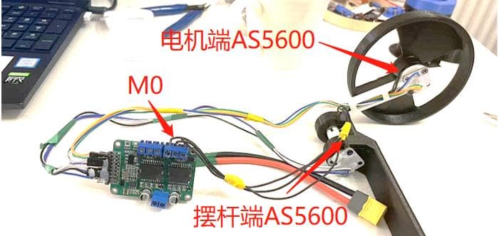
As long as you have a DengFOC V3 (you can search for ToanTech on Taobao to enter the store to purchase, or make it yourself based on the open-source materials from the DengFOC open-source repository (opens in a new tab)), you can quickly assemble this project. The default supply voltage for the project is 16.8V. In addition to DengFOC, the other electronic components mainly consist of a 2204 brushless motor and two AS5600 encoders. The wiring table is as follows:
| Component | Wiring Location |
|---|---|
| 2204 Motor | DengFOC M0 Position |
| Motor-side AS5600 | SDA0, SCL0, 3V3, GND |
| Pendulum-side AS5600 | SDA1, SCL1, 3V3, GND |
4 Part Manufacturing
The main components of the inverted pendulum are 3D printed. Download the drawings in the folder and print them at 100% infill.
All other components can be found in the "BOM table" in the open-source folder.
4 Download the Program
Download the DengFOC_Inverted_Pendulum.ino program from the project folder, open it with the Arduino IDE, connect to DengFOC via serial port, and upload it using the same method as a regular Arduino.
6 Debugging
5.1 Initial Value Specification
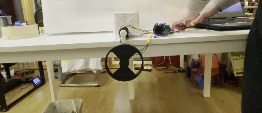
After completing the program download, the initial angle of the momentum wheel inverted pendulum needs to be calibrated. Before calibration, ensure that the inverted pendulum is in a hanging state, as shown in the figure:
Next, comment out the statement in the program to ensure that the motor does not move after power-on:
motor.move(target_voltage);
After commenting, power on the DengFOC controller and press the "Reset" button on the board. After the motor is calibrated, the serial monitor in Arduino IDE will output a series of values. These values are the initial angle of the inverted pendulum that we need. Record this angle and replace the number 3.83 shown in the figure:

After the replacement, uncomment the line motor.move(target_voltage); to allow the motor to move, re-upload the program, and power on and reset. At this point, the inverted pendulum should operate normally.
5.2 LQR Parameter Tuning
In general, the three parameters of the LQR controller (i.e., adjust_ang, adjust_p_vel, and adjust_motor_vel) do not need to be adjusted. You only need to use the same motors as mine and print the parts with the same infill density as mine, and there is no need to adjust these three parameters. However, if you replace the motors or if the infill density of the flywheel is different from mine, you will need to retune these three parameters to achieve stability.
Since I have implemented a quick tuning function via serial port in the program, the tuning method is very simple. Below are the tuning steps:
(1) If you need to tune the LQR parameter for balancing the inverted pendulum angle:
Enter "A+parameter" in the Arduino IDE serial monitor, e.g., to set the parameter to 40, enter A40.
(2) If you need to tune the LQR parameter for balancing the inverted pendulum angular velocity:
Enter "P+parameter" in the Arduino IDE serial monitor, e.g., to set the parameter to 5, enter P5.
(3) If you need to tune the LQR parameter for the motor speed of the inverted pendulum:
Enter "M+parameter" in the Arduino IDE serial monitor, e.g., to set the parameter to 0.01, enter M0.01.
6 Other Notes
If you replace the motor with a different one, you need to reset the motor's pole pairs.
If the self-stabilizing effect is opposite to the tipping direction, it indicates that the motor's three-phase wires are connected in reverse, causing the motor's rotation direction to be reversed. Simply swap any two of the three-phase wires to correct it.
Files by @ToanTech, at commit 2d61e88, read from GitHub in your browser. Hardware license: GPL-3.0-only; software license: GPL-3.0-only. Robotheca doesn't review code: read it before running it.