Balancio-Kit
An ultra-low-cost self-balancing robot that can run a neural network to stay balanced and be controlled wirelessly, built for teaching RL, ML, AI and control.
- Other
- Open source
- Works with AI
- arduino
- 3D model (URDF)
- 3D printable
Suggested by Robotheca, created by @udesa-linar (opens in a new tab), from github.com/udesa-linar/balancio-kit (opens in a new tab). Pinned to commit bae6838 (opens in a new tab).
- Hardware license
- MIT (opens in a new tab)
- Software license
- MIT (opens in a new tab)
- Commercial use
- Allowed
Photo and 3D model
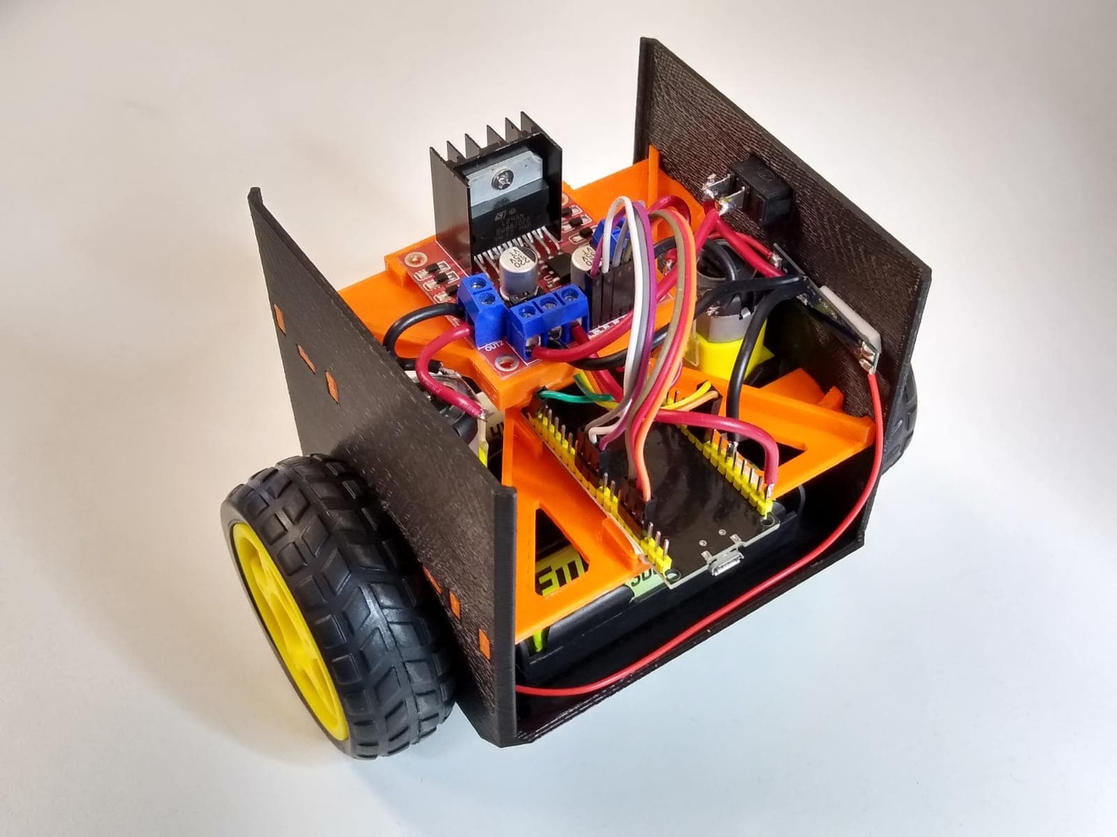
3D preview converted from github.com/udesa-linar/balancio-kit at bae6838, under MIT. View the original files from GitHub (340 KB) (opens in a new tab)
- Weight
- 0.244 kg
What it can do
Written by Robotheca from the project's documents.
- Self-balances on two wheels using an IMU and a control loop, with a PID controller or a reinforcement learning agent selectable in config.h
- Wirelessly controlled from a phone via Bluetooth through an MIT App Inventor application
- Can run a neural network (TinyML) to maintain balance, per the project description
- Simulation in Python is available as an optional component for testing control code
Works with AI
Found by Robotheca in the project's files at commit bae6838, its robot.yaml and Robotheca's notes on its documents. Never guessed; Robotheca doesn't run the code.
“Self-balances on two wheels using an IMU and a control loop, with a PID controller or a reinforcement learning agent selectable in config.h”
Robotheca's notes: What it can do“Can run a neural network (TinyML) to maintain balance, per the project description”
Robotheca's notes: What it can do
Bill of materials
This repository has no parts list Robotheca can read yet.
Build guide
The creator's steps, each with its instructions.
- 13D print one of the robot versions
- 2Snap the parts into their final positions
- 3Secure the motors with zip ties and/or glue
- 4Connect the components following the wiring diagram
- 5Install the Arduino IDE and configure the ESP32 board
- 6Install the Arduino libraries (MPU6050, PS3 Controller Host, EloquentTinyML)
- 7Upload a test example to the microcontroller
- 8Install the Python simulation environment with Conda (optional)
- 9Calibrate the IMU
- 10Calibrate the equilibrium angle
- 11Calibrate the PID constants
The guide appears here as you scroll.
Guide by @udesa-linar (README_EN.md), under MIT.
Wiring and electronics
Notes written by Robotheca from the project's documents.
Main parts
- NodeMCU ESP32 microcontroller board
- MPU6050 inertial measurement unit (IMU)
- Two 6V gear motors with wheels
- L298N H-bridge motor driver
- Two 18650 batteries with holder
- BMS FCD-2S-2 battery management board and a battery charger
- On/off switch and DuPont wires
Connections
- The wiring diagram is provided as an image (Plano_1.3.png) in the repository, not described in text.
- The 12V jumper on the motor driver must be removed during PID tuning, per the calibration steps.