Balance-Tech Self-Balancing Bike
A two-wheel self-balancing bicycle-like robot that balances with a reaction wheel using a Kalman filter and LQR control, and can move and turn.
- Other
- Open source
- arduino
- 3D printable
Suggested by Robotheca, created by @pxmkv (opens in a new tab), from github.com/pxmkv/Balance-Tech (opens in a new tab). Pinned to commit ea44e93 (opens in a new tab).
- Hardware license
- BSD-2-Clause (opens in a new tab)
- Software license
- BSD-2-Clause (opens in a new tab)
- Commercial use
- Allowed
Photo and 3D model
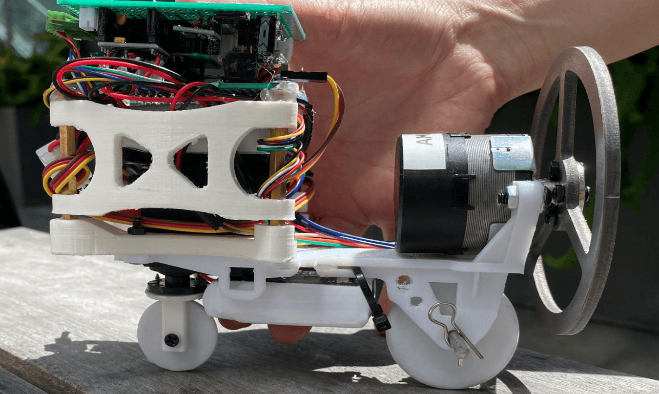
3D preview converted from github.com/pxmkv/Balance-Tech at ea44e93, under BSD-2-Clause. View the original files from GitHub (6.5 MB) (opens in a new tab)
What it can do
Written by Robotheca from the project's documents.
- Balances as a two-wheel self-balancing bike using a reaction (momentum) wheel driven by a motor
- Moves forward and backward with a rear drive motor and can turn with a steering servo
- Estimates tilt by fusing accelerometer and gyro readings with a Kalman filter
- Uses LQR state feedback to control the momentum wheel
- Stops the momentum wheel motor when tilt exceeds 22 degrees
- Controlled by a Bluetooth gamepad (Bluepad32) or by serial commands for live gain tuning and calibration
- Balancing loop runs at about 100 Hz
Bill of materials
This repository has no parts list Robotheca can read yet.
Build guide
The guide appears here as you scroll.
Guide by @pxmkv (readme.md), under BSD-2-Clause.
More guides
Wiring and electronics
Notes written by Robotheca from the project's documents.
Main parts
- WeMOS D1 mini ESP32 (ESP-WROOM-32) microcontroller
- MPU6050 IMU (accelerometer and gyro) read over I2C
- Momentum wheel motor with quadrature encoder for speed and position
- Drive motor driven through an H-bridge
- Steering servo
- Buck converter for adjustable supply and AMS1117 regulator for the MCU
- Battery power supply, wired low to reduce center of mass
Connections
- Momentum wheel PWM on GPIO 26, enable/switch on GPIO 18, direction on GPIO 5
- Encoder channels A and B on GPIO 19 and 23
- Drive motor H-bridge PWM on GPIO 33 and GPIO 4
- Steering servo PWM on GPIO 17 at 50 Hz
- IMU on I2C with SDA on GPIO 21 and SCL on GPIO 22
- Full wiring is given in the schematic PDF in the schematic folder
