ALTO 3D Printed 6 Axis Robotic Arm
A 3D printed desktop high precision 6 axis robotic arm controlled over USB with a Python API.
- Robot arm
- Open source
- 3D printable
Suggested by Robotheca, created by @liaochikon (opens in a new tab), from github.com/liaochikon/ALTO-3D-Printed-6-Axis-Robotic-Arm (opens in a new tab). Pinned to commit f83587b (opens in a new tab).
- Hardware license
- MIT (opens in a new tab)
- Software license
- MIT (opens in a new tab)
- Commercial use
- Allowed
Some folders have their own license: firmware/Drivers/CMSIS/ (Apache-2.0).
This repository contains executable files that Robotheca doesn't check. Only run them if you trust the creator.
Which files (1 firmware image)
Photo and 3D model
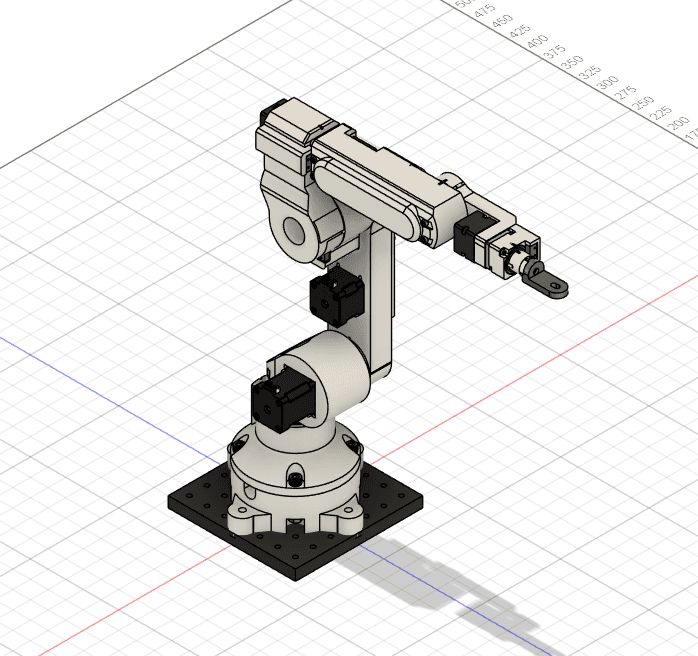
3D preview converted from github.com/liaochikon/ALTO-3D-Printed-6-Axis-Robotic-Arm at f83587b, under MIT. View the original files from GitHub (19.5 MB) (opens in a new tab)
- Degrees of freedom
- 6
What it can do
Written by Robotheca from the project's documents.
- Six-axis 3D printed robotic arm controlled through joint angles and motion commands.
- Computes forward and inverse kinematics in the firmware for Cartesian and joint motion.
- Can be driven from a computer over USB serial, using a command reference file or the Python API.
- Python API lets code set speed, acceleration, motion mode and joint angles, then start and stop the arm.
- Each joint has a limit switch used to calibrate its origin (0 degrees).
Bill of materials
This repository has no parts list Robotheca can read yet.
Build guide
The guide appears here as you scroll.
Guide by @liaochikon (README.md), under MIT.
Wiring and electronics
Notes written by Robotheca from the project's documents.
Main parts
- STM32F407VG microcontroller board as the control box.
- NEMA17 stepper motors on joints 1 to 3.
- NEMA14 stepper motors on joints 4 to 6.
- CSF-11 harmonic drive reducers on joints 1 to 3 and CSF-8 reducers on joints 4 to 6.
- Limit switch on every joint.
- SN65HVD230 CAN bus transceiver.
- 12V 100W power supply and a 12V to 5V converter.
Connections
- Control box connects to a computer through USB, where the arm appears as a USB device.
- Stepper drivers are connected to the STM32 over a CAN bus through the SN65HVD230 transceiver.
- The 12V power supply feeds the motors, and a 12V to 5V converter supplies the logic electronics.