ZoroBot3 Micromouse
A high-performance micromouse maze-solving robot built around an STM32F4 with high-resolution magnetic encoders, suction, and many LEDs.
- Wheeled
- Open source
- 3D printable
Suggested by Robotheca, created by @OPRobots (opens in a new tab), from github.com/OPRobots/ZoroBot3 (opens in a new tab). Pinned to commit 1056343 (opens in a new tab).
- Hardware license
- GPL-3.0-only (opens in a new tab)
- Software license
- GPL-3.0-only (opens in a new tab)
- Commercial use
- Allowed
Photo and 3D model
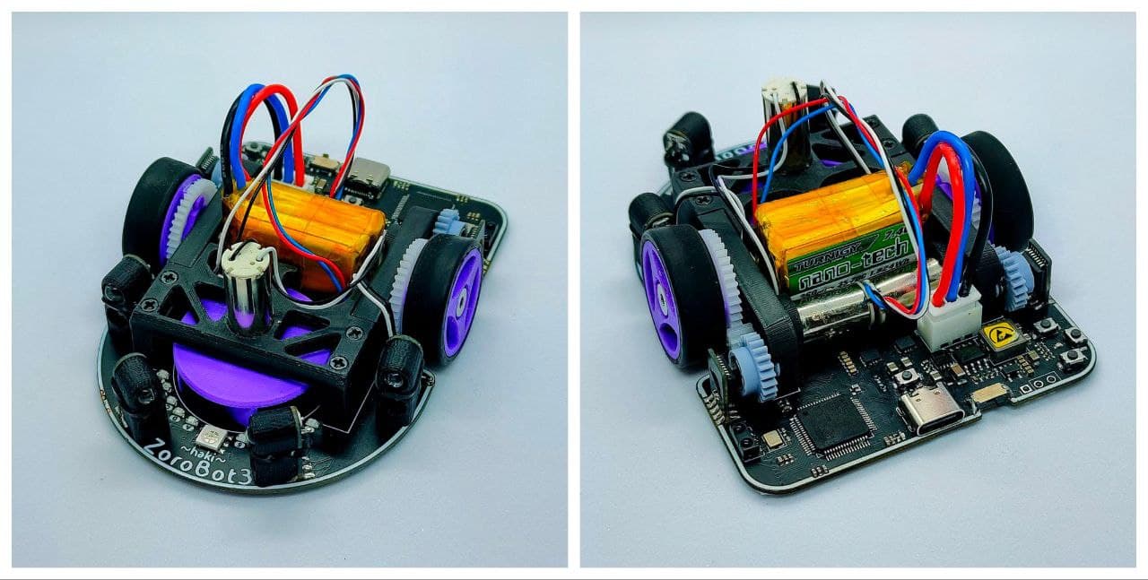
3D preview converted from github.com/OPRobots/ZoroBot3 at 1056343, under GPL-3.0-only. View the original files from GitHub (1.2 MB) (opens in a new tab)
What it can do
Written by Robotheca from the project's documents.
- Micromouse robot that explores and solves mazes, with wall-following, exploration and floodfill-based solving modes.
- Wall-following to the right or left, plus hard-coded movement sequences.
- Speed and steering control loops (linear speed, angular speed, front and side control) run every 1 ms.
- Turns follow sine-acceleration profiles for smoother motion.
- Position is reset when a side wall is lost, to improve navigation.
- Suction fan and many LEDs for decoration and feedback.
Bill of materials
This repository has no parts list Robotheca can read yet.
Build guide
The guide appears here as you scroll.
Guide by @OPRobots (README.md), under GPL-3.0-only.
More guides
Wiring and electronics
Notes written by Robotheca from the project's documents.
Main parts
- STM32F405RGT6 microcontroller running at 168 MHz.
- MP6551 motor driver, switching at 20 kHz.
- LSM6DSRTR gyroscope (IMU), read over SPI.
- AS5145B-HSST magnetic encoders, one per wheel.
- Four SFH-4550 infrared emitters and four ST-1KL3A infrared receivers as wall sensors.
- TSSP77038TR 38 kHz infrared receiver.
- AO3400 MOSFETs switching the sensor emitters and the suction fan.
- CN3903 charger and ME611C33M5G LDO regulator.
- 2S LiPo battery, 260 mAh, 35-70C.
- Two 7.4 V coreless 8520 DC motors.
Connections
- Gyroscope is connected over SPI.
- Analog sensor values are read through DMA.
- Encoder values are read in hardware quadrature using two timers.
- Sensor emitters are switched on and off by MOSFETs to filter out ambient light.