Scribbot
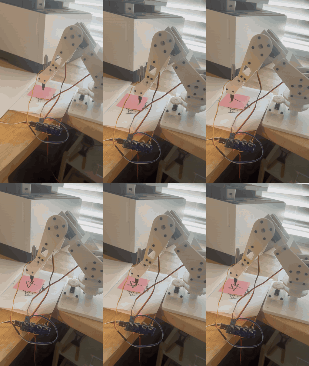
A low-cost, mostly 3D-printed desktop robot arm that draws on a sticky note and can copy a doodle seen by a webcam.
- Robot arm
- Open source
- arduino
- 3D printable
Suggested by Robotheca, created by @imjbassi (opens in a new tab), from github.com/imjbassi/Scribbot (opens in a new tab). Pinned to commit c2392ae (opens in a new tab).
- Hardware license
- MIT (opens in a new tab)
- Software license
- MIT (opens in a new tab)
- Commercial use
- Allowed
Photo and 3D model
3D preview converted from github.com/imjbassi/Scribbot at c2392ae, under MIT. View the original files from GitHub (11.7 MB) (opens in a new tab)
- Height
- 127 mm
What it can do
Written by Robotheca from the project's documents.
- Draws squares, circles, stars and text (up to 8 characters) on a 3x3 inch sticky note
- Four joints: base, shoulder, elbow and wrist, driven over USB serial with single-letter commands
- Keeps the pen vertical using inverse kinematics on the Nano
- Copies a hand-drawn doodle from a webcam image onto the sticky note via a Python vision script
- Test program moves each joint slowly and in steps, with outputs off at startup
Bill of materials
This repository has no parts list Robotheca can read yet.
Build guide
The creator's steps, each with its instructions.
- 1Print fit coupons for servo bodies, bearing pocket and slider clearance
- 2Print servo mounting-hole templates
- 3Print servo mount plates and bearing carrier
- 4Assemble the bearing turntable
- 5Mount the base servo and mesh the gears
- 6First power-on: wiring and centering the base servo
- 7Base calibration and repeatability tests
- 8Fit the shoulder horn and mount the shoulder stage
- 9Assemble the elbow stage
- 10Fit the pen holder and assemble the wrist stage
- 11Calibrate joints and upload the drawing software
- 12Assemble the camera stand and set up vision
The guide appears here as you scroll.
Guide by @imjbassi (README.md), under MIT.
More guides
Wiring and electronics
Notes written by Robotheca from the project's documents.
Main parts
- Arduino Nano microcontroller
- PCA9685 16-channel servo driver board
- Four hobby servos: MG90S for base and wrist, MG996R for shoulder and elbow
- 5 V servo power supply connected to the PCA9685 screw terminal
- Logitech Brio 101 webcam on a printed stand for the copy-a-drawing mode
Connections
- Nano 5V connects to PCA9685 VCC
- Nano GND connects to PCA9685 GND
- Nano A4 connects to PCA9685 SDA
- Nano A5 connects to PCA9685 SCL
- Servo power goes only into the PCA9685 green screw terminal, never through the Nano
- PCA9685 channels: 0 base, 1 shoulder, 2 elbow, 3 wrist


