Project files
6 KB
Machine-translated by Robotheca from the original in Chinese (opens in a new tab). License: Apache-2.0 (opens in a new tab).
Overall Design
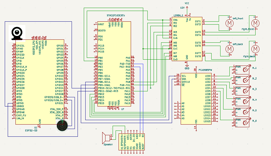
Other notes: The Raspberry Pi's USB port is connected to the camera.
Hardware Modules and Tools List
| Module | Description | Price (CNY) |
|---|---|---|
| STM32f103C8T6 | Control board, serving as the central control unit. | 15 |
| Car Chassis | Metal chassis with JGB37520 motors featuring Hall-effect encoders and Mecanum omni-directional wheels | 350 |
| L298N Quad Driver | L298N motor driver for four-wheel drive | 28 |
| Voice Control Module | ASR PRO voice control board | 25 |
| Power and Conversion Board | 12V power supply with DC interface. Includes 12V to 5V and 3.3V conversion board. | 40 |
| Camera | OV2640 camera module | 10 |
| Robotic Arm | Robotic arm components with servos. Uses standard MG996 servos; serial bus servos or servo motors can be used for better performance, though they are more expensive. | 200 |
| Servo Driver | PCA9685 16-channel servo driver | 16 |
| JQ6500 | MP3 player | 15 |
| OLED Screen | OLED screen for displaying debugging/monitoring information | 10 |
| TOF Distance Sensor | OpenMV expansion module to compensate for OpenMV's limitations in distance measurement | 10 |
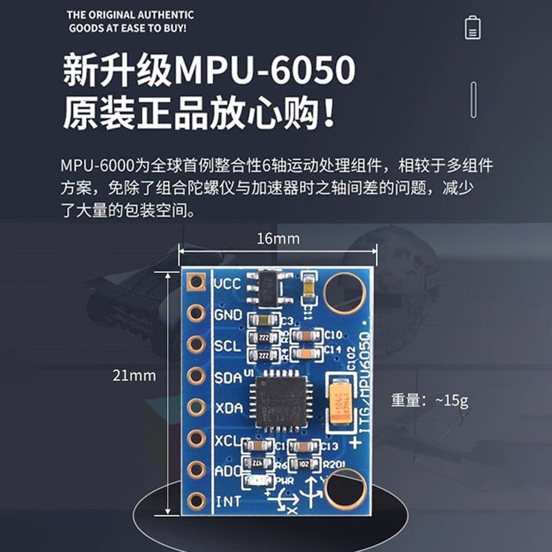
| Gyroscope | MPU6050, used for monitoring the car's direction | 15 |
| ESP32-S3-CAM | Used to create a Wi-Fi network for connecting to a mobile app | 35 |
Assembly Result
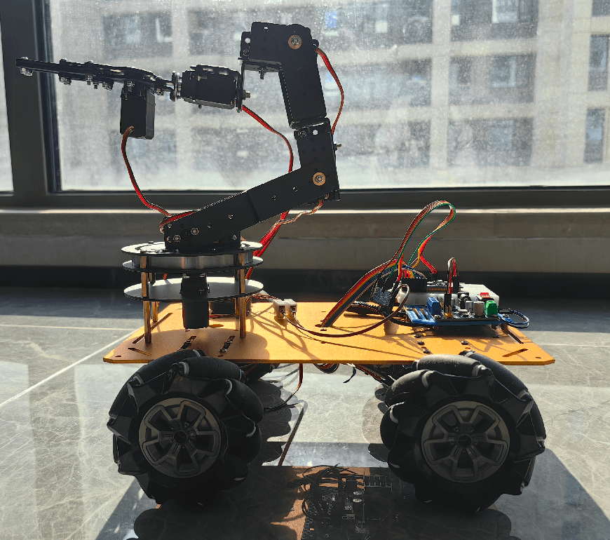
Module Description
Voice Recognition Module
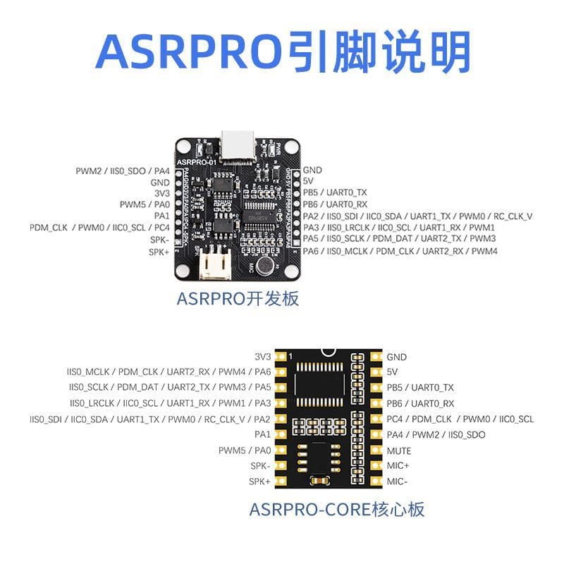
Use the voice recognition module for speech recognition and convert it into commands to control the robot.
Control Center - STM32 Board

The STM32 board serves as the central control unit, receiving voice commands, converting them into motor driver instructions, and sending them to the motor driver. At the same time, it interfaces with the Raspberry Pi. After the Raspberry Pi performs image recognition, it sends control instructions back to the STM32, which drives the robotic arm servos based on the instructions.
The IO port allocation is as follows:
| GPIO | Interface | Function Description | Indicator Light |
|---|---|---|---|
| PA11 | Motor Driver IN1 | Left front motor control 1 | |
| PA10 | Motor Driver IN2 | Left front motor control 2 | |
| PA9 | Motor Driver IN3 | Left rear motor control 1 | |
| PA8 | Motor Driver IN4 | Left rear motor control 2 | |
| PB15 | Motor Driver IN5 | Right front motor control 1 | |
| PA14 | Motor Driver IN6 | Right front motor control 2 | |
| PB13 | Motor Driver IN7 | Right rear motor control 1 | |
| PA12 | Motor Driver IN8 | Right rear motor control 2 | |
| PA2 | UART2 TX to ASR Board PA6 RX | Voice board serial communication | |
| PA3 | UART2 RX to ASR Board PA5 TX | Voice board serial communication | |
| PB6 | IIC communication to Raspberry Pi | Raspberry Pi communication | |
| PB7 | IIC communication to Raspberry Pi | Raspberry Pi communication | |
| PB8 | IIC communication to Servo Driver | Servo driver communication | |
| PB9 | IIC communication to Servo Driver | Servo driver communication | |
| PB10 | UART3 TX to ESP8266 RX0 | PS2 controller communication | |
| PB11 | UART3 RX to ESP8266 TX0 | PS2 controller communication | |
| PB0 | Left side motor enable | Motor usage control | |
| PB1 | Right side motor enable | Motor usage control |
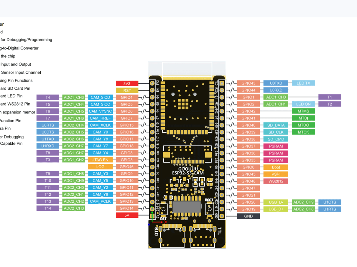
ESP32-S3-CAM
Car Chassis
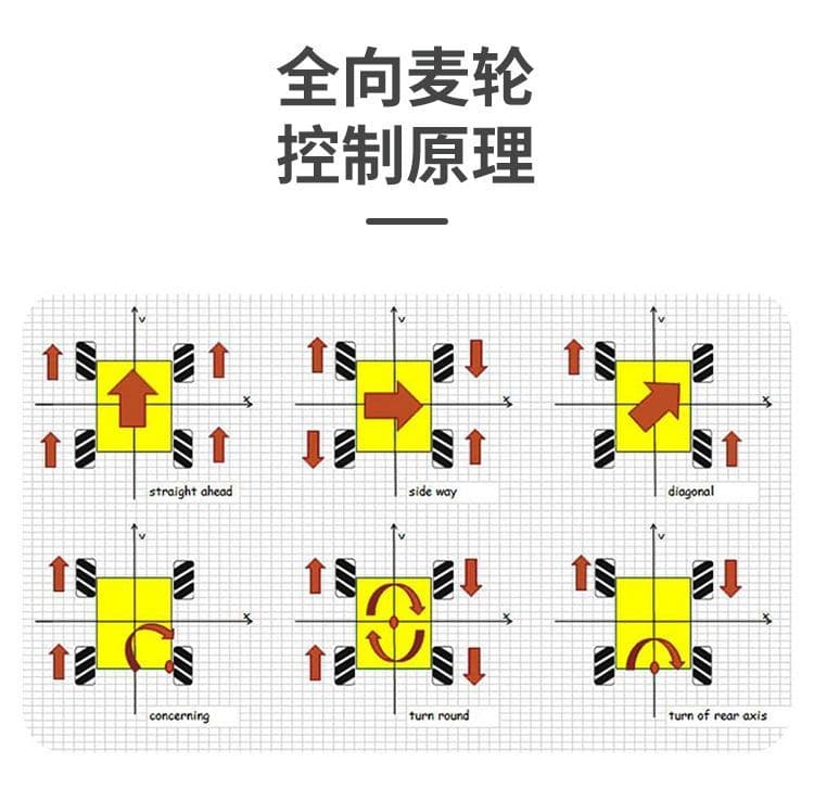
The car chassis is assembled using the Pinduoduo Taobao chassis, JGB37 520 motor, and caster wheels. Pinduoduo also offers complete sets, which are slightly more expensive.


Motor Driver Module
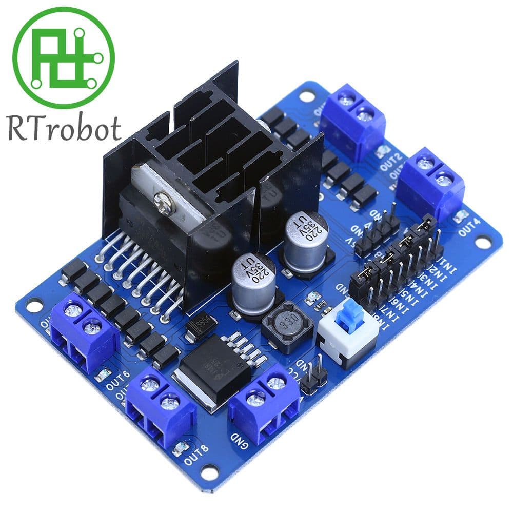
Uses the L298N motor driver to control the four motors of the car, enabling four-wheel drive.
Input voltage: 12 V Output voltage: 5 V, used to power the control board and other modules.
Robotic Arm
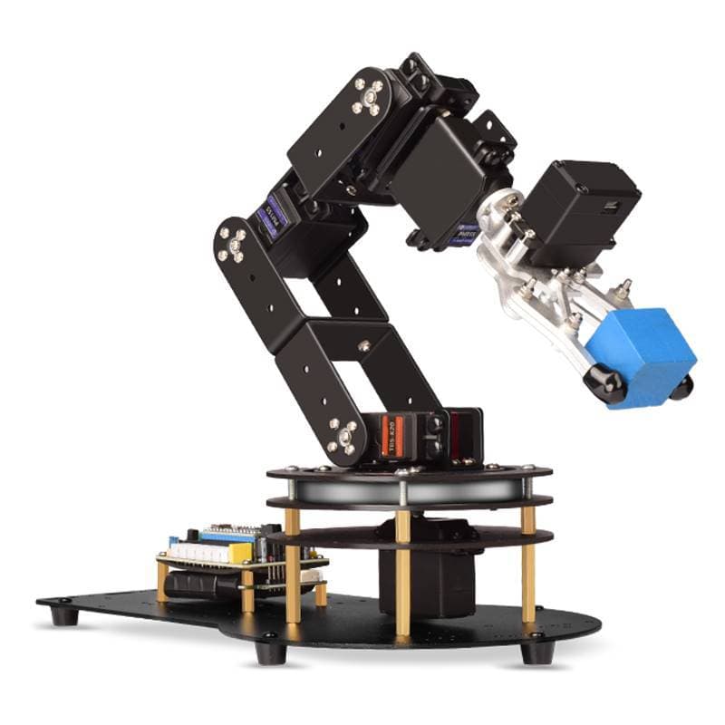
The robotic arm is assembled from parts purchased from Pinduoduo. It features six 180-degree servos.
PCA9685 Servo Driver
 16-channel servo driver
Vision Module
Uses OpenMV as the vision module
 Tutorial reference: https://singtown.com/openmv/ (opens in a new tab)
6-axis gyroscope
OLED Display
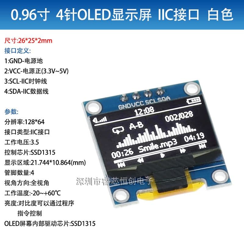
GY53L0X TOF Rangefinder

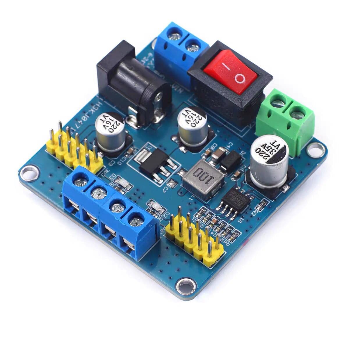
Power and Voltage Conversion Board
The car operates at three voltage levels: 12V, 5V, and 3.3V. It is recommended to use a 12V power supply and convert the voltage using a voltage conversion board.
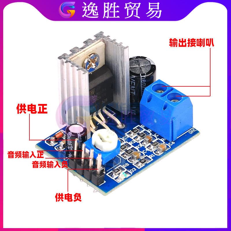
Audio amplifier
If the volume is too low, you can further amplify the sound with this amplifier.
Raspberry Pi
 Raspberry Pi 4B+ performs image recognition and processing using the camera.
Hardware Design Tool: KiCAD
Installation: https://docs.kicad.org/5.1/zh/getting_started_in_kicad/getting_started_in_kicad.html (opens in a new tab)
Assembly Notes
- 1 Plan the motor driver and IO port connections and the robot car's direction in advance to avoid incorrect connections.
- 2 Before assembling the robotic arm, debug the servos to ensure the arm's range of motion is within the servo's control range.
- 3 Some ASRPro boards from certain sellers are fragile; do not power them with the voltage converted from a 12V lithium battery. If this is the case, request a refund or replacement.
- 4 When connecting ASRPRO with STM32 and STM32 with PCA9685, ensure that the ground wires are connected together.
Files by @coregiu, at commit c9d4b8e, read from GitHub in your browser. Hardware license: Apache-2.0; software license: Apache-2.0. Robotheca doesn't review code: read it before running it.