Roverling Mk II
A cheap, multipurpose mobile robotic platform for research, development, education and fun, with 3D-printed parts and an 18V power tool battery.
- Wheeled
- Open source
- 3D printable
Suggested by Robotheca, created by @MarkMakies (opens in a new tab), from github.com/MarkMakies/Roverling-Mk-II (opens in a new tab). Pinned to commit 22ffc5a (opens in a new tab).
- Hardware license
- CC-BY-SA-4.0 (opens in a new tab)
- Software license
- CC-BY-SA-4.0 (opens in a new tab)
- Commercial use
- Allowed
Photo and 3D model
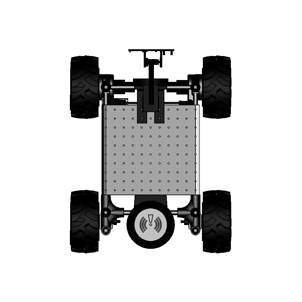
3D preview converted from github.com/MarkMakies/Roverling-Mk-II at 22ffc5a, under CC-BY-SA-4.0. View the original files from GitHub (11.8 MB) (opens in a new tab)
- Height
- 250 mm
- Weight
- 3.5 kg
- Weight
- 440 mm
What it can do
Written by Robotheca from the project's documents.
- Mobile wheeled platform intended for research, education and experimentation, with outdoor navigation goals such as checking gates and patrolling paddocks.
- Can be driven by a 2.4GHz RC transmitter without other modules: steering via ailerons, camera tilt via elevator, reverse via GEAR, RC mode toggled by FLAPS.
- Telemetry aggregates GPS, IMU, motor velocity and current, RC channels, PIR, sonar range, battery level and LoRa signal quality at about 1800 bps.
- Accepts encrypted LoRa commands from a base station, which forwards telemetry and commands over WiFi to an MQTT broker.
- Desktop mapping module plots real-time tracking from the MQTT feed over an image; an onboard Raspberry Pi 4B with camera module is planned for later video capture.
Bill of materials
This repository has no parts list Robotheca can read yet.
Build guide
The guide appears here as you scroll.
Guide by @MarkMakies (README.md), under CC-BY-SA-4.0.
More guides
Wiring and electronics
Notes written by Robotheca from the project's documents.
Main parts
- Raspberry Pi Pico (RP2040) motion processor handling RC input, motor quadrature decoding and inter-MCU communication.
- Raspberry Pi Pico RP2040 telemetry processor aggregating sensor data for LoRa transmission.
- Raspberry Pi Pico W telemetry gateway bridging LoRa to MQTT over WiFi.
- Two RP2040-Zero boards in the design, plus a Raspberry Pi 4 Model B with Camera Module 3 for later stages.
- Adafruit PA1616D GPS/GLONASS breakout with magnetic-mount antenna.
- AltIMU-10 v6 IMU with gyro, accelerometer, compass and altimeter.
- Two SX1262 LoRa modules at 915 MHz with a 1/4 wave antenna.
- HC-SR501 PIR motion sensor and XL-MaxSonar-EZ0 sonar range finder.
- Two LMD18200 H-bridge motor drivers, with motor current sensing and quadrature encoders.
- DC-DC adjustable 5A step-down module, powered from an 18V power tool battery.
- 2.4GHz 6-channel RC receiver and decoder.
Connections
- Motion processor and telemetry processor exchange data over an inter-MPU communication link (Comms.py).
- Telemetry processor connects to the LoRa module and the GPS and IMU modules.
- Telemetry gateway receives LoRa packets and publishes them over WiFi to an MQTT broker.
- Motor drivers are H-bridges driven from the motion processor, with quadrature decoders and current sensors on each of two motor channels.
- Power is distributed through a protoboard with power breakouts and screw terminal blocks; the step-down converter supplies the logic electronics.
- KiCad schematics are in the R202 and R301 folders; no PCB layout has been designed yet, so wiring follows the prototype photos and schematic.