Robotics 101
An open-source introductory robotics course by Imperial College Robotics Society, designed to be run in hackspaces, after-school clubs and university societies.
- Other
- Open source
Suggested by Robotheca, created by @ICRS (opens in a new tab), from github.com/ICRS/101 (opens in a new tab). Pinned to commit 3426405 (opens in a new tab).
- Hardware license
- CC-BY-4.0 (opens in a new tab)
- Software license
- CC-BY-4.0 (opens in a new tab)
- Commercial use
- Allowed
This repository contains executable files that Robotheca doesn't check. Only run them if you trust the creator.
Photo and 3D model
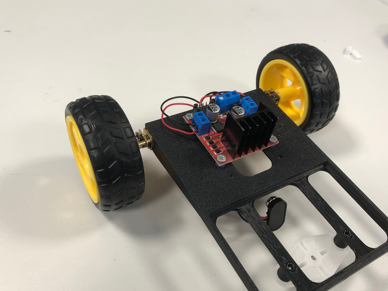
3D preview converted from github.com/ICRS/101 at 3426405, under CC-BY-4.0. View the original files from GitHub (8.2 MB) (opens in a new tab)
What it can do
Written by Robotheca from the project's documents.
- Drives two motors so the robot can move forward and turn, controlled by signals on microcontroller pins.
- Uses a switch to start motor movement in the 2024 and 2025 versions of the build.
- Balances on a ball wheel at the rear, allowing it to move and spin on the spot.
- An IR sensor can be added as an extra to detect obstacles and stop the robot.
Bill of materials
This repository has no parts list Robotheca can read yet.
Build guide
The guide appears here as you scroll.
Guide by @ICRS (README.md), under CC-BY-4.0.
More guides
Wiring and electronics
Notes written by Robotheca from the project's documents.
Main parts
- Microcontroller: an Arduino in the 2023 build and an ESP32 or ESP32-based S2 mini microcontroller in later builds.
- Motor driver board (L298N-style) with heatsink, driving two DC motors.
- Two DC motors with shaft adaptors and wheels.
- A 9V battery in a holder supplies the motor driver.
- A breadboard with resistors, LEDs, pushbutton or switch, and optional IR sensor.
- A 2023 custom devkit board PCB with KiCad design and Gerber files.
Connections
- Battery ground (black) goes to the breadboard negative rail; battery positive (red) goes to the motor driver +12V input.
- Motor driver +5V connects to the microcontroller VBUS pin with a male-to-male jumper; microcontroller GND goes to the breadboard negative rail.
- Motor driver Input1 to Input4 connect to specific microcontroller pins; the order matters, and the 2024 and 2025 builds use different pin numbers.
- A switch on the microcontroller pin 34 (2024 build) with two large-value resistors, or a button on pin D2 (2023 build) with a pulldown resistor.
- An IR sensor connects VCC to 3.3V, GND to GND, and its OUT pin to a signal pin.
Schematics, boards and diagrams
- 2016/docs/assets/img/pin_connections.pngDiagram
- 2016/docs/assets/img/ultrasound_circuit.pngDiagram
- 2023/101 Devkit Board/PCB/101 PCB/101 PCB.kicad_pcbKiCad
- 2023/101 Devkit Board/PCB/101 PCB/101 PCB.kicad_schKiCad
- 2023/101 Devkit Board/PCB/101 PCB/Fabrication Files/101 Gerbers/101 Gerbers.zipGerber (PCB manufacturing)
- 2023/101 Devkit Board/PCB/101 PCB/Fabrication Files/101 GerbersGerber (PCB manufacturing)
- 2023/Images/button-circuit.pngDiagram
- 2023/Images/electronics-schematic-labelled.pngDiagram
- 2023/Images/electronics-schematic.pngDiagram
- 2023/Images/led-circuit-off.jpgDiagram
- 2023/Images/led-circuit-on.jpgDiagram
- 2023/Images/LED-on-breadboard-schematic.pngDiagram
- 2023/Images/switch-schematic.pngDiagram
- 2024-Autumn/images/motor-connections.jpgDiagram
- 2024-Autumn/images/power-connections-2.jpgDiagram
- 2024-Autumn/images/power-connections.jpgDiagram
- 2024-Winter/Images/button-circuit.pngDiagram
- 2024-Winter/Images/electronics-schematic-labelled.pngDiagram
- 2024-Winter/Images/electronics-schematic.pngDiagram
- 2024-Winter/Images/led-circuit-off.jpgDiagram
- 2024-Winter/Images/led-circuit-on.jpgDiagram
- 2024-Winter/Images/LED-on-breadboard-schematic.pngDiagram
- 2024-Winter/Images/switch-schematic.pngDiagram
- 2025-Autumn/Images/wiring_diagram.pngDiagram
- 2025-Autumn/Images/wiring_image.jpgDiagram
- 2025-Winter/Images/wiring_diagram.pngDiagram
- 2025-Winter/Images/wiring_image.jpgDiagram
- 2026-Autumn/Robotics101.fzzFritzing


