Project files
5 KB
Machine-translated by Robotheca from the original in Chinese (opens in a new tab). License: Apache-2.0 (opens in a new tab).
Servo Placement
The PingTi arm has 8 servos in total, including 2 ST-3250 (50 kg·cm) servos and 6 ST-3215 (30 kg·cm) servos. The servo placement is as follows:

Link placement
The PingTi arm has 10 links in total. The placement of each link is shown below:

USB Board Connection
Please refer to the image below to connect the power supply and servos.
Note: The
V1port is labeledDC6V-9V, but after consulting Feetech technical support, it was confirmed that 12V power can be connected safely.

Configuring the Servos with LeRobot
A. Install the LeRobot library and find the USB ports
Refer to the Install LeRobot section of the official https://github.com/huggingface/lerobot/blob/main/examples/10_use_so100.md#b-install-lerobot (opens in a new tab) tutorial.
You should also find the USB ports by following the instructions in the Find the USB port associated with each arm section of the https://github.com/huggingface/lerobot/blob/main/examples/10_use_so100.md#1-find-the-usb-ports-associated-to-each-arm (opens in a new tab) tutorial.
B. Configuring the Servos with LeRobot
The following script demonstrates how to configure a servo. The configuration script performs the following two tasks:
- Sets the servo's ID to
1 - Sets the servo's position to
2048
python lerobot/scripts/configure_motor.py \
  --port /dev/tty.usbmodem58760432961 \
  --brand feetech \
  --model sts3215 \
  --baudrate 1000000 \
  --ID 1
Then unplug your servo and insert the second servo (the second servo should be an ST-3250 servo), and set its ID to 2. Here you can continue to use the --model sts3215 parameter, because both models share the same SDK and control table.
python lerobot/scripts/configure_motor.py \
  --port /dev/tty.usbmodem58760432961 \
  --brand feetech \
  --model sts3215 \
  --baudrate 1000000 \
  --ID 2
Repeat this process until all servos have their IDs set to 8. Note that the 2 ST-3250 servos should have IDs 2 and 3. You can also refer to the servo placement diagram above.
C. Attach the horns to all 8 servos
You can refer to the official LeRobot video for attaching the horns to all 8 servos. The video link is here: Add Motor Horn to servos (opens in a new tab)
PingTi Robotic Arm Assembly
Base Assembly
Refer to the SO-100 assembly video to assemble the base link and the servo (ID 1). Specifically, you should check Step 4.1 to Step 4.4 in this video (opens in a new tab).
Shoulder Assembly
Connect the servo cables The Shoulder joint consists of two ST-3250 servos. You should connect all four cables before placing the servos into their slots, as shown below.

Place the servos into the base_yaw_link slots Place the ID 2 servo in the left slot and the ID 3 servo in the right slot. Secure the servos with four M2x5 screws. As shown below
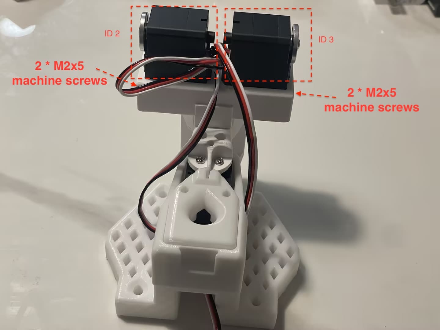
Connect the shoulder link to the servo horn Use eight M3x6 machine screws to attach the Shoulder link to the servo horn. Note that the Shoulder link should be attached to the servo horn vertically, and the servo slot at the end of the Shoulder link should face forward. As shown below.

Elbow Assembly
Connect the servo cables The Elbow joint consists of 2 ST-3215 servos with IDs ID 4 and ID 5. You should connect the cables correctly before placing the servos into their slots. As shown in the figure below

Insert into the Shoulder link slot and attach the elbow link As shown in the figure below, place the ID4 servo into the left slot and the ID5 servo into the right slot, and secure the servos with 4 M2x5 screws. At the same time, use 8 M3x6 machine screws to attach the Elbow link to the servo horns.
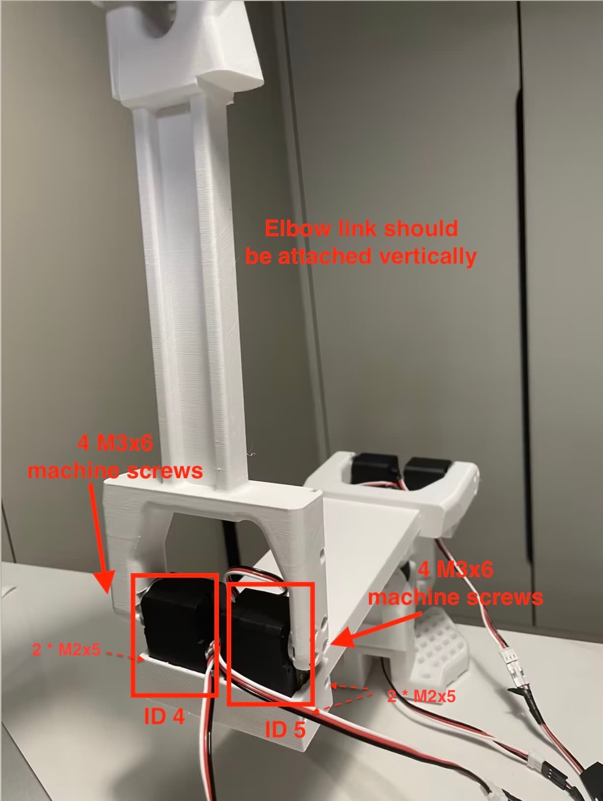
Wrist & Gripper Assembly
Refer to the SO-100 assembly video to assemble the wrist link, gripper link, and servos (you will use servos with IDs 6, 7, and 8).
Specifically, you should start from Step 4.9 to Step 4.12 in this video (opens in a new tab).
SO-100 Leader Arm Assembly
Refer to the SO-100 leader arm assembly video (opens in a new tab)
Footnote
SO-100-related assembly tutorials can also be found on Bilibili, for example 30-minute SO-100 assembly, step-by-step video tutorial for the follower arm (opens in a new tab)
Files by @nomorewzx, at commit 9108729, read from GitHub in your browser. Hardware license: Apache-2.0; software license: Apache-2.0. Robotheca doesn't review code: read it before running it.