PingTi Arm
A low-cost, human-arm-scale open-source robotic arm compatible with Lerobot, based on the SO-100 arm, with a 600mm span and up to 500g payload.
- Robot arm
- Open source
- Works with AI
- LeRobot
- 3D model (URDF)
- 3D printable
Suggested by Robotheca, created by @nomorewzx (opens in a new tab), from github.com/nomorewzx/PingTi-Arm (opens in a new tab). Pinned to commit 9108729 (opens in a new tab).
- Hardware license
- Apache-2.0 (opens in a new tab)
- Software license
- Apache-2.0 (opens in a new tab)
- Commercial use
- Allowed
Photo and 3D model
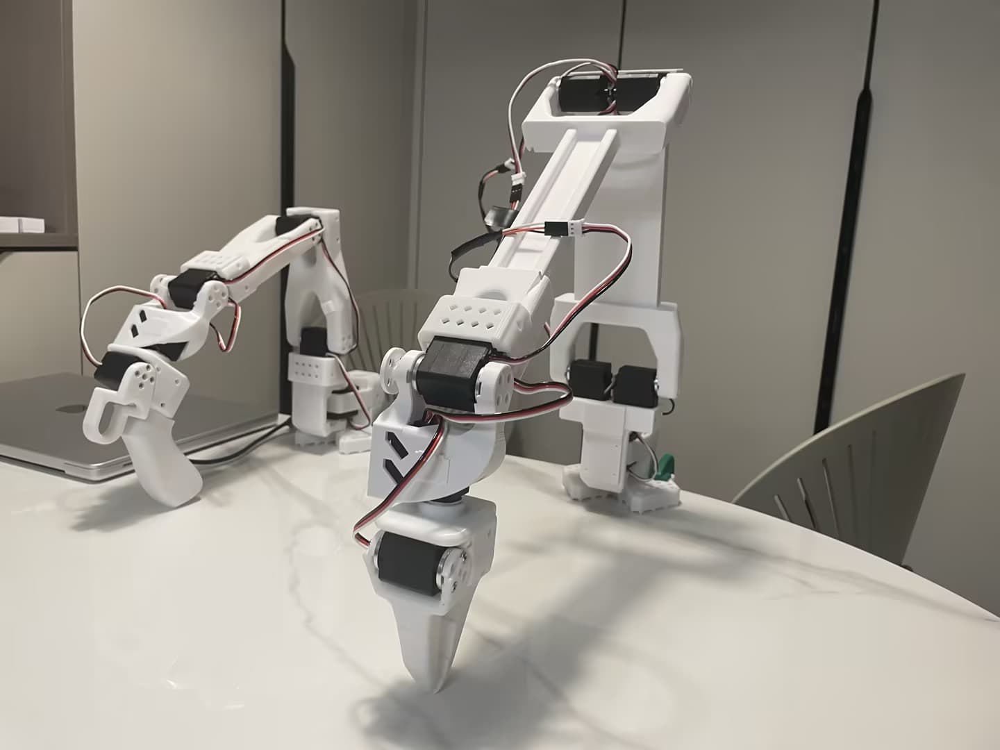
3D preview converted from github.com/nomorewzx/PingTi-Arm at 9108729, under Apache-2.0. View the original files from GitHub (6.6 MB) (opens in a new tab)
- Reach
- 600 mm
- Payload
- 500 g
What it can do
Written by Robotheca from the project's documents.
- Robotic arm with about 600mm span (excluding end effector), designed at human arm scale.
- Payload up to 500g at maximum arm span, per the English README.
- Can be set up as a leader-follower pair, with SO-100 as the leader arm.
- Compatible with LeRobot for teleoperation and data collection via the pingti_lerobot_bridge SDK.
- Has a gripper driven by a servo (IDs 6, 7 and 8 are the wrist and gripper servos).
Works with AI
Found by Robotheca in the project's files at commit 9108729, its robot.yaml and Robotheca's notes on its documents. Never guessed; Robotheca doesn't run the code.
Runs LeRobot
Stated in robot.yaml“Compatible with LeRobot for teleoperation and data collection via the pingti_lerobot_bridge SDK.”
Robotheca's notes: What it can do“Install the LeRobot library, following its tutorial.”
Robotheca's notes: How to run it“Configure each servo with LeRobot's configure_motor.py script, setting its ID (1 to 8) with --brand feetech, --model sts3215 and --baudrate 1000000.”
Robotheca's notes: How to run it
Bill of materials
5 parts5 of 5 parts shown
| # | Component | Quantity | Est. price | Supplier |
|---|---|---|---|---|
| 1 | STS3250 Servo | 2 | €59.25 | Alibaba: buy STS3250 Servo (EU shop), opens in a new tab |
| 2 | STS3215 Servo (12V,30 kg.cm) | 6 | €13 | Alibaba: buy STS3215 Servo (12V,30 kg.cm) (EU shop), opens in a new tab |
| 3 | Motor Control Board | 1 | €6.79 | Amazon: buy Motor Control Board (EU shop), opens in a new tab |
| 4 | Table Clamp 2pcs | 1 | €8 | Amazon: buy Table Clamp 2pcs (EU shop), opens in a new tab |
| 5 | Dupont Wire | 1 | €6.99 | Amazon: buy Dupont Wire (EU shop), opens in a new tab |
Parts total: €218.28. Read from docs/BOM_List.md at the pinned commit.
Build guide
The creator's steps, each with its instructions.
- 1Print the arm links and parts
- 2Assemble the arm
The guide appears here as you scroll.
Guide by @nomorewzx (README.md), under Apache-2.0.
More guides
Wiring and electronics
Notes written by Robotheca from the project's documents.
Main parts
- 8 servos: 2 ST-3250 (50kg.cm) for the shoulder and 6 ST-3215 (30kg.cm) for the other joints.
- Feetech USB drive board (motor control board) used to drive the servos from a computer.
- 12V power supply connected to the board's power port.
- Table clamps and Dupont wires are listed as parts.
Connections
- Servo wires are connected to the servos before they are placed into the slots of the links.
- Servos are chained on the Feetech USB drive board, which connects to the computer over USB.
- The board's V1 power port is labeled DC6V-9V, but the documents say a 12V supply can be connected safely after checking with Feetech support.
Cables and connectors
From the parts list.
- Dupont Wire × 1