Pacer v1 Track Pacer Car
A 3D-printed, 1/10-scale autonomous pacer robot that runs alongside track and field athletes.
- Self-driving 1:10
- Open source
- arduino
Suggested by Robotheca, created by @aidanahn (opens in a new tab), from github.com/aidanahn/pacer-v1 (opens in a new tab). Pinned to commit 0aa207a (opens in a new tab).
- Hardware license
- MIT (opens in a new tab)
- Software license
- MIT (opens in a new tab)
- Commercial use
- Allowed
Photo and 3D model
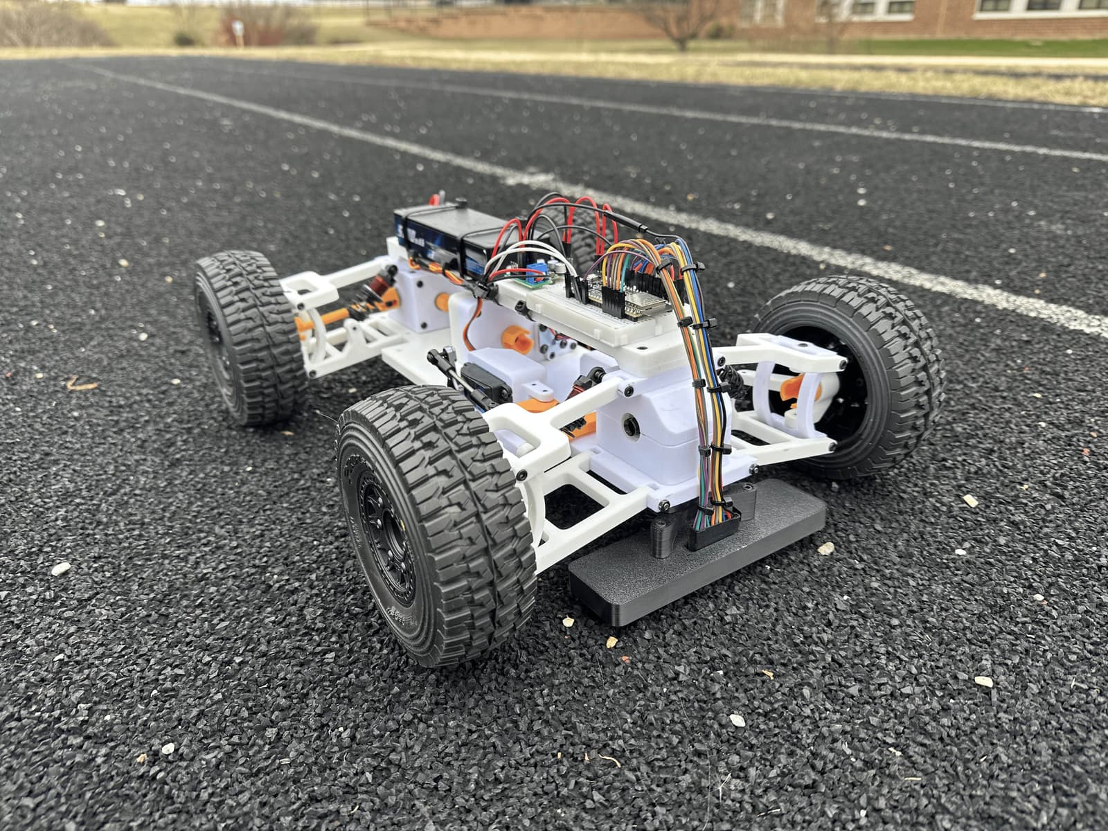
3D preview converted from github.com/aidanahn/pacer-v1 at 0aa207a, under MIT. View the original files from GitHub (4.9 MB) (opens in a new tab)
What it can do
Written by Robotheca from the project's documents.
- Designed as a 3D-printed, 1/10-scale autonomous pacer robot for track and field.
- Described as autonomous, with a 35kg servo for steering and a sensored brushless motor for drive.
Bill of materials
26 parts26 of 26 parts shown
| # | Component | Quantity | Est. price | Supplier |
|---|---|---|---|---|
| Bill of Materials | ||||
| 1 | 10x15x4mm Bearing | 16 | – | – |
| 2 | 5x10x4mm Bearing | 2 | – | – |
| 3 | M3 Tie Rod End | 4 | – | – |
| 4 | 35kg Servo | 1 | – | – |
| 5 | Servo Horn | 1 | – | – |
| 6 | Sensored Brushless DC Motor | 1 | – | – |
| 7 | Wheels | 4 | – | – |
| 8 | LiPo Battery | 1 | – | – |
| 9 | 120mm Timing Belt | 1 | – | – |
| 10 | 20T GT2 Timing Pulley | 1 | – | – |
| 11 | 40T GT2 Timing Pulley | 1 | – | – |
| 12 | 55mm Touring Shocks | 4 | – | – |
| 13 | Differential | 1 | – | – |
| 14 | Pinion Gear | 1 | – | – |
| 15 | Breadboard | 1 | – | – |
| 16 | ESP32-S3-DevKitC-1-N8R8 | 1 | – | – |
| 17 | Power Distribution Module | 1 | – | – |
| 18 | 5V Buck Converter | 1 | – | – |
| 19 | AS5600 | 1 | – | – |
| 20 | Diametrically Magnetized On-Axis Magnet | 1 | – | – |
| 21 | XT60 to T-Plug Adapter | 1 | – | – |
| 22 | Jumper Wires | 33 | – | – |
| 23 | 5V Buck Converter | 1 | – | – |
| 24 | PETG Filament | – | – | – |
| 25 | Differential Oil | – | – | – |
| 26 | Shock Oil | – | – | – |
26 of 26 needed parts have no price in the source, so there is no parts total. Read from README.md at the pinned commit.
Build guide
The guide appears here as you scroll.
Guide by @aidanahn (README.md), under MIT.
Wiring and electronics
Notes written by Robotheca from the project's documents.
Main parts
- ESP32-S3-DevKitC-1-N8R8 microcontroller board.
- 35kg servo for steering.
- Sensored brushless DC motor for drive.
- AS5600 magnetic angle sensor with a diametrically magnetized on-axis magnet.
- LiPo battery with an XT60 to T-Plug adapter.
- Power Distribution Module and 5V buck converters.
- Breadboard and jumper wires for prototyping connections.
Connections
- The AS5600 sensor reads a diametrically magnetized on-axis magnet, so the magnet sits on the rotating shaft.
- Jumper wires connect parts on the breadboard, with power taken from the LiPo battery through the Power Distribution Module and 5V buck converters.
Cables and connectors
From the parts list.
- XT60 to T-Plug Adapter × 1
- Jumper Wires × 33