Otto DIY Humanoid Robot
An open-source humanoid robot designed for learning and AI integration, featuring assembly guides and firmware documentation.
- Humanoid
- Open source
- Works with AI
- 3D printable
Suggested by Robotheca, created by @txp666 (opens in a new tab), from github.com/txp666/ottodiy-docs (opens in a new tab). Pinned to commit 8d4824d (opens in a new tab).
- Hardware license
- MIT (opens in a new tab)
- Software license
- MIT (opens in a new tab)
- Commercial use
- Allowed
This repository contains executable files that Robotheca doesn't check. Only run them if you trust the creator.
Photo
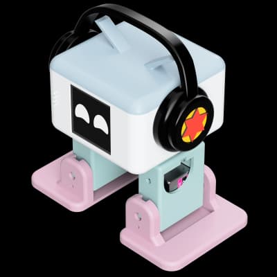
What it can do
Written by Robotheca from the project's documents.
- Humanoid walking and balancing
- AI voice interaction via microphone and speaker
- Servo-driven joints for arms, legs, head and feet
- Wi-Fi and WebSocket control for remote commands
- Camera-based face detection and recognition (camera version)
- Charging via USB Type-C
Works with AI
Found by Robotheca in the project's files at commit 8d4824d, its robot.yaml and Robotheca's notes on its documents. Never guessed; Robotheca doesn't run the code.
“AI voice interaction via microphone and speaker”
Robotheca's notes: What it can do
Bill of materials
4 parts4 of 4 parts shown
| # | Component | Quantity | Est. price | Supplier |
|---|---|---|---|---|
| 1 | 身体 | 1 | – | – |
| 2 | 头部 | 1 | – | – |
| 3 | 腿部 | 2 | – | – |
| 4 | 脚部 | 2 | – | – |
4 of 4 parts have no price in the source, so there is no parts total. Read from docs/bom.md at the pinned commit.
Build guide
The guide appears here as you scroll.
Guide by @txp666 (README.md), under MIT. The English translation is by Robotheca, shared under the same license.
More guides
Wiring and electronics
Notes written by Robotheca from the project's documents.
Main parts
- ESP32-S3 microcontroller board
- I2S MEMS microphone
- Class-D audio amplifier and speaker
- Li-ion battery with charging circuit
- Power management IC and voltage regulators
- Type-C USB port for power and data
Connections
- Servos connected to ESP32-S3 PWM pins via 3-pin connectors (brown GND, red VCC, yellow signal)
- Microphone wired to I2S bus and power pins
- Speaker connected to amplifier output and ground
- Battery connected to power management circuit with protection diode
- Camera module connected via I2C and power pins when present
- ESP32-S3 UART and USB for flashing and serial monitor