Micro Racer Car
A small ESP32-based PCB racing car that can be driven by a remote, a keyboard, or a neural network trained on colour sensor data.
- Self-driving 1:10
- Open source
- Works with AI
- 3D printable
Suggested by Robotheca, created by @StuckAtPrototype (opens in a new tab), from github.com/StuckAtPrototype/Racer (opens in a new tab). Pinned to commit 846dd3e (opens in a new tab).
- Hardware license
- Apache-2.0 (opens in a new tab)
- Software license
- Apache-2.0 (opens in a new tab)
- Commercial use
- Allowed
This repository contains executable files that Robotheca doesn't check. Only run them if you trust the creator.
Which files (1 firmware image)
Photo and 3D model
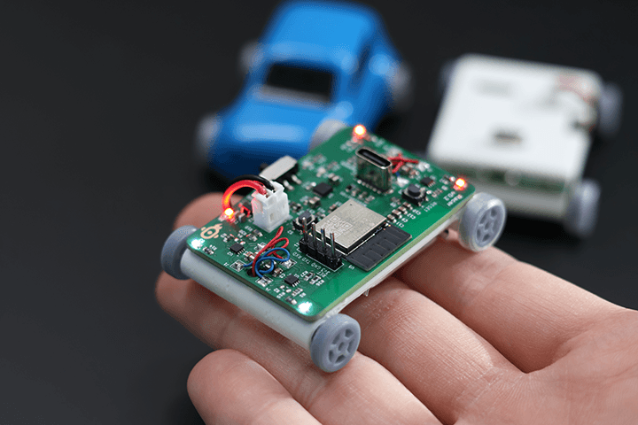
3D preview converted from github.com/StuckAtPrototype/Racer at 846dd3e, under Apache-2.0. View the original files from GitHub (16.8 MB) (opens in a new tab)
What it can do
Written by Robotheca from the project's documents.
- Drives a small car by sending motor commands over Bluetooth Low Energy from a keyboard script or hardware remote.
- Includes a neural network embedded in the car, trained on color sensor readings to classify colors (white, black, red, green).
- Can be trained on labeled color sensor data with a Python training script.
- Can be driven with the w, a, s, d keys through a Python script for debugging.
Works with AI
Found by Robotheca in the project's files at commit 846dd3e, its robot.yaml and Robotheca's notes on its documents. Never guessed; Robotheca doesn't run the code.
“Includes a neural network embedded in the car, trained on color sensor readings to classify colors (white, black, red, green).”
Robotheca's notes: What it can do“To train the neural network, put labeled color data in color_data.txt and run python trainer.py.”
Robotheca's notes: How to run it
Bill of materials
32 parts32 of 32 parts shown
| # | Component | Quantity | Est. price | Supplier |
|---|---|---|---|---|
| 1 | U9 TPS631000DRLR | 1 | – | – |
| 2 | R6,R26,R28,R29,R9,R1,R27,R11,R4 10K | 9 | – | – |
| 3 | C2,C16,C20,C18,C5,C6,C19,C1,C22 10uF | 9 | – | – |
| 4 | S2 SWITCH_0SMTRLFS | 1 | – | – |
| 5 | C7,C12,C13,C24,C15,C3,C8,C14,C4,C23,C11,C25 0.1uF | 12 | – | – |
| 6 | R2 806 | 1 | – | – |
| 7 | U6 AP2205 | 1 | – | – |
| 8 | R23 1.43K | 1 | – | – |
| 9 | J9 Conn_02x03_SMT | 1 | – | – |
| 10 | Q1 BSS138 | 1 | – | – |
| 11 | D9 LED_RED | 1 | – | – |
| 12 | R17,R22,R18 5K1 | 3 | – | – |
| 13 | LED1,LED3,LED5,LED4,LED2 IN-PI15TAT5R5G5B | 5 | – | – |
| 14 | D8 LED_GREEN | 1 | – | – |
| 15 | U4,U1,U2,U3 A3908 | 4 | – | – |
| 16 | J12 JST 2.0 BATT | 1 | – | – |
| 17 | P1 USB_C_Plug_USB2.0 | 1 | – | – |
| 18 | TH1 TH 10K | 1 | – | – |
| 19 | U5 ESP32-H2-MINI-1 | 1 | – | – |
| 20 | R3 91 | 1 | – | – |
| 21 | R5 470 | 1 | – | – |
| 22 | L1 1uH | 1 | – | – |
| 23 | C10 1uF | 1 | – | – |
| 24 | R21,R20 330 | 2 | – | – |
| 25 | D5 TPD1E10B06 | 1 | – | – |
| 26 | S1 JS102011SAQN | 1 | – | – |
| 27 | R24 75K | 1 | – | – |
| 28 | U7 MCP73833 | 1 | – | – |
| 29 | C17 22uF | 1 | – | – |
| 30 | R16 1M | 1 | – | – |
| 31 | C9 47uF | 1 | – | – |
| 32 | C21 2.2uF | 1 | – | – |
32 of 32 parts have no price in the source, so there is no parts total. Read from hardware/racer/racer-v1.0-BOM.csv at the pinned commit.
Build guide
The guide appears here as you scroll.
Guide by @StuckAtPrototype (README.md), under Apache-2.0.
More guides
Wiring and electronics
Notes written by Robotheca from the project's documents.
Main parts
- ESP32-H2-MINI-1 module as the main microcontroller.
- A3908 motor driver ICs, four of them, for driving the motors.
- IN-PI15TAT5R5G5B addressable LEDs, five of them.
- Color sensor used for classifying colors.
- TPS631000 buck-boost converter and AP2205 regulator for power.
- MCP73833 battery charger with a JST 2.0 battery connector.
- USB-C connector.
- Thermistor (TH1, 10K) and BSS138 MOSFET, plus status LEDs and tactile switches.
Connections
- Motor driver outputs connect to the car's two motor sides, controlled by the ESP32 firmware.
- Power path runs from the battery connector through the charger and regulators to the ESP32 and drivers.
- Other connections are documented only in the KiCad schematic files, which this summary did not analyze in detail.
Cables and connectors
From the parts list.
- J12 JST 2.0 BATT × 1