Project files
8 KB
Machine-translated by Robotheca from the original in Japanese (opens in a new tab). License: MIT (opens in a new tab).
M5Stack_Walk-chan
A bipedal robot built with M5Stack.
Overview
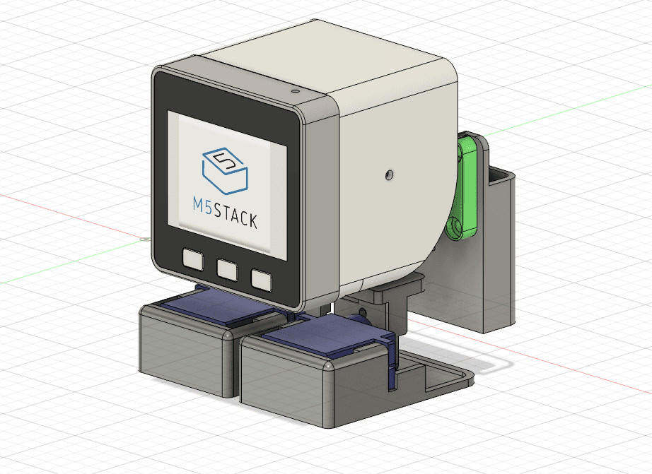
M5Stack Walk-chan (hereinafter Walk-chan) is a bipedal walking robot that uses the M5Stack as its control board. It aims to achieve a small bipedal robot in the M5Stack size, similar to Otto DIY, and was designed in time for the first anniversary birthday party of "Stack-chan," born in 2022.
The key to this type of bipedal robot is reliably shifting the center of gravity toward the supporting leg when one leg is lifted. Since the M5Stack body alone does not shift its center of gravity sufficiently, a linear motion mechanism that moves the battery mounted on the back from side to side has been added. This achieves stable walking motion.
For detailed background on the build and walking videos, please refer to the note article "二足歩行スタックチャン(Walk chan)を作ってみた (opens in a new tab)".
Features
- Bipedal robot powered by M5Stack
- Battery linear motion mechanism (rack and pinion) for shifting the center of gravity
- Uses a total of five SG90 servo motors
- Includes a board that converts from the M5Stack M-Bus to a servo PWM connector
- Body data provided as STL files for 3D printing and assembled STEP format
- Sample sketches for Arduino IDE / PlatformIO
- Displays an avatar (eyes) on the LCD, enabling effects synchronized with walking
Hardware
Required Parts
| Part | Quantity | Notes |
|---|---|---|
| M5Stack Basic / Gray / Fire など | 1 | Control board |
| SG90 compatible servo | 5 | 2 for legs (legs and ankles) + 1 for battery movement |
| Board for M5Stack Walk-chan | 1 | See pcb/ in this repository |
| 3D printed parts | Set | See 3Ddata/stl/ |
| Lithium-ion battery (NP-40 etc.) | 1 | A battery for compact digital cameras is recommended |
| M3 screws and nuts | As needed | Used for gear guides, etc. |
Servo Assignment
The sample sketch assigns GPIO pins and servos as follows.
| Servo | GPIO | LEDC Channel | Role |
|---|---|---|---|
| FootR | 2 | 0 | Right ankle (left-right tilt) |
| FootL | 12 | 1 | Left ankle (left-right tilt) |
| LegR | 0 | 2 | Right leg (forward-backward swing) |
| LegL | 15 | 3 | Left leg (forward-backward swing) |
| Ballast | 13 | 4 | Battery center-of-gravity shift |
Adjust the cent* and rot* constants in the sketch to match each servo's center position and range of motion, depending on individual variation and how the robot is assembled.
3D Model
The 3D data for the body parts is stored in 3Ddata/.
Walk-chan_assembled.step: Assembled STEP file (editable in Fusion360 and similar tools)stl/: Split STL files for 3D printingbracket_front.stl,bracket_rear.stl: Front and rear bracketsfoot_l.stl,foot_r.stl: Left and right feetjoint_l.stl,joint_r.stl: Left and right leg jointsgear.stl,rack_gear.stl,gear_guide.stl: Gears for the battery linear motion mechanismholder_NP-40.stl: NP-40 battery holdershell.stl: Outer shell
Note: An assembly guide has not been created yet, so for now, please assemble the robot while checking the assembled STEP file in CAD. Pay attention to part interference and the mounting direction of the servos.
PCB for SG90
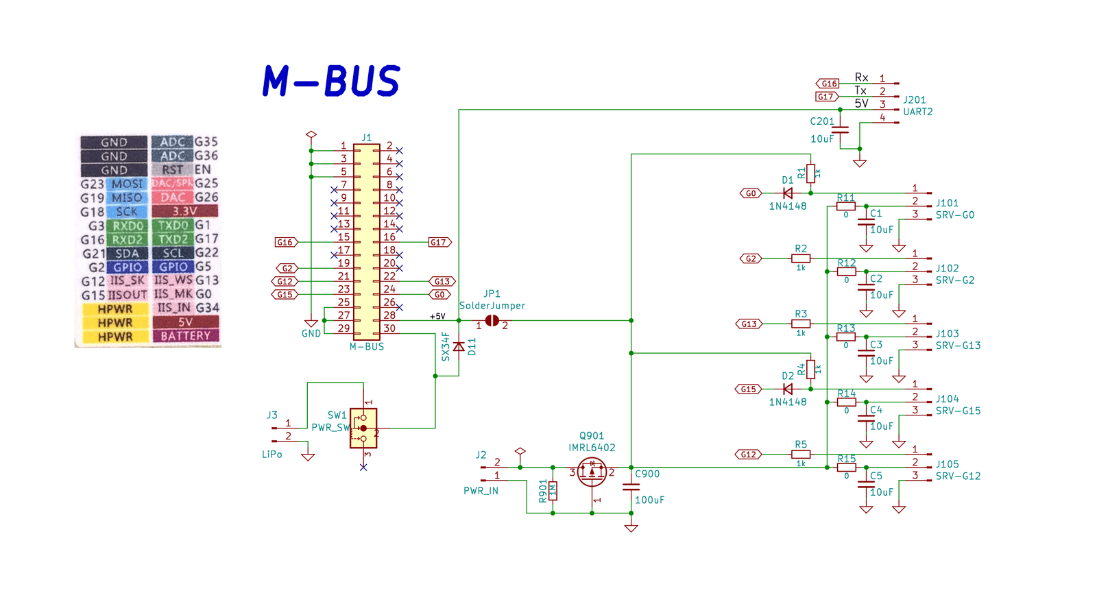
The board data that converts from the M5Stack M-Bus to a PWM connector for the servo is included in pcb/.
Main board specifications
- Outputs the PWM signal for each servo directly from the M5Stack's M-Bus connector
- No servo control IC is used; driven directly by the M5Stack's GPIO / LEDC outputs
- Grove-compatible connectors are brought out, allowing expansion with external sensors and other devices
- Servo power can be selected by solder jumper: "supplied from the connector" or "supplied from the 5V of the M-Bus"
- A 2-pin pin header allows connecting "5V power for the servos" and "a lithium-ion battery for the M5Stack"
- The M5Stack itself can be powered on and off with a physical switch on the side
Sample Code
The sample sketches are stored in examples/M5_walk-chan_WalkTest/.
M5_walk-chan_WalkTest.ino: Main sketch. Handles the walking sequence, avatar display, and monitoring of battery level and charging status.clappyavator.h/clappyavator.cpp: Libraries that draw the avatar (eyes) shown on the M5Stack's LCD.ip5306.h: Register definitions for the power management IC (IP5306) built into the M5Stack.
Walking sequence overview
- Shift the ballast (battery) left and right to move the center of gravity over the supporting leg.
- Tilt the body by angling the ankle of the supporting leg inward and the ankle of the swinging leg outward.
- Swing the swinging leg forward and backward.
- Return the ankles to their original position and lower the swinging leg to the ground.
- Repeat the same steps on the other side to continue walking.
After performing one cycle of the initial motion described above within setup(), the robot repeats the alternating left-right walking motion within loop().
Charging Mode
When the IP5306 (0x75) is detected at power-on and the device is charging, the robot enters the "HOME POSITION" adjustment mode. Pressing button B switches to the normal walking demo. This safety feature exists because servo movement during charging can cause power load issues and unstable operation.
Build and Flash
- Prepare the required parts and print the 3D-printed components.
- Following the STEP or STL files, assemble the servos, gears, and battery.
- Manufacture and solder the circuit board, and connect the M5Stack and each servo.
- Open
M5_walk-chan_WalkTestin the Arduino IDE or PlatformIO, then build and upload it for the M5Stack.- Required library:
M5Stacklibrary
- Required library:
- Power on and confirm that the avatar appears on the M5Stack LCD and that Walk-chan starts walking.
Notes
- The servo connectors on the board are placed so they do not interfere with the bracket. Pay attention to the connector orientation when wiring.
- The battery case is fixed to the rack gear with screws. Currently, a holder for NP-40 lithium-ion batteries is included, but the case can be replaced to use other power sources such as AAA dry cells.
- The left-right battery movement mechanism is a replaceable structure that fits into the bracket.
- Because this is a two-legged walking robot, it may fall over depending on the floor surface and balance. On first operation, leave ample space around the robot and check it at low speed.
License
Files by @tomorrow56, at commit 0de1575, read from GitHub in your browser. Hardware license: MIT; software license: MIT. Robotheca doesn't review code: read it before running it.