Line Following Robot with Ball-Putting Mechanism
An Arduino-controlled line following robot with PID steering, obstacle detection and a servo-driven ball-putting mechanism on a laser-cut metal chassis.
- Wheeled
- Open source
- arduino
- 3D printable
Suggested by Robotheca, created by @Nagi-1010 (opens in a new tab), from github.com/Nagi-1010/Line-Following-Robot-with-Ball-Putting-Mechanism (opens in a new tab). Pinned to commit 4def2cb (opens in a new tab).
- Hardware license
- MIT (opens in a new tab)
- Software license
- MIT (opens in a new tab)
- Commercial use
- Allowed
Photo and 3D model
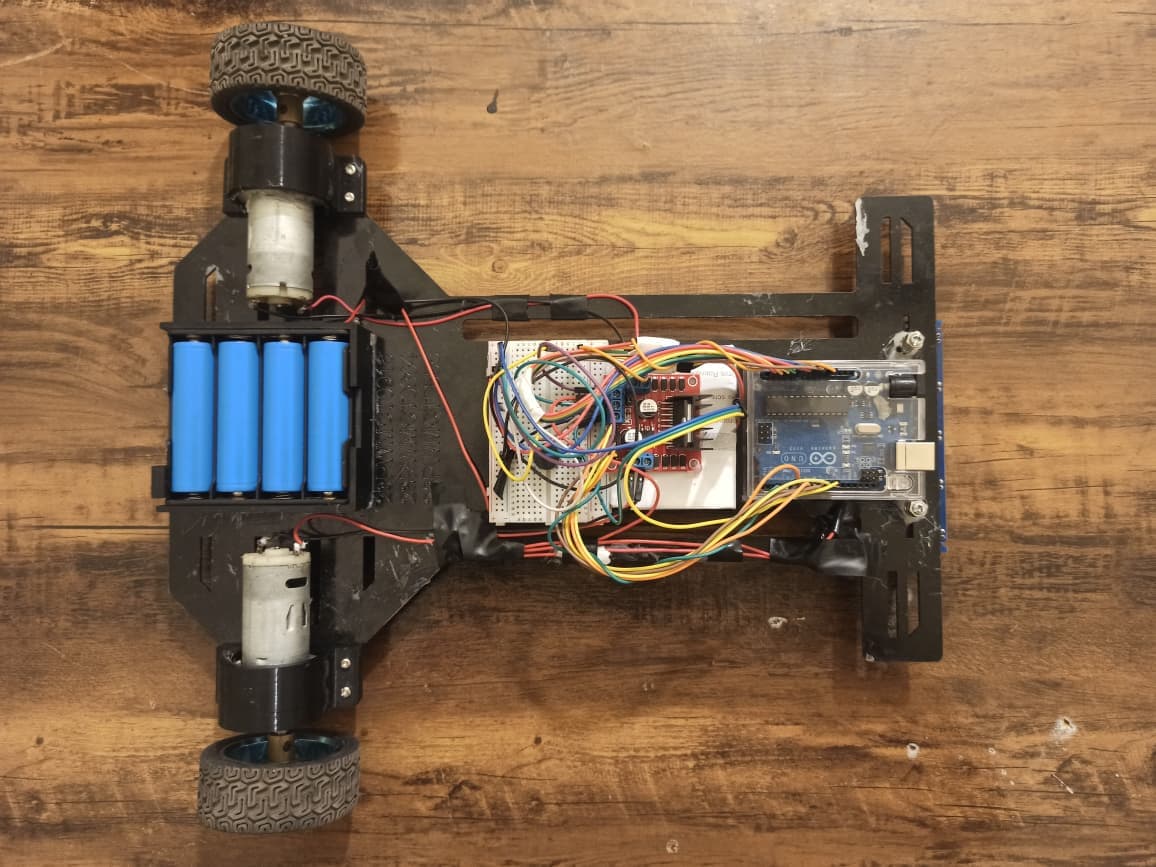
3D preview converted from github.com/Nagi-1010/Line-Following-Robot-with-Ball-Putting-Mechanism at 4def2cb, under MIT. View the original files from GitHub (85 KB) (opens in a new tab)
What it can do
Written by Robotheca from the project's documents.
- Follows a black line on the ground using an IR sensor array and PID-based control logic.
- Drives two DC geared motors through an L298N motor driver.
- Detects obstacles with an ultrasonic sensor.
- Operates a servo-based ball-putting mechanism.
- Uses a custom laser-cut metal chassis of 35 x 30 cm with 3D-printed mounts.
Bill of materials
This repository has no parts list Robotheca can read yet.
Build guide
The guide appears here as you scroll.
Guide by @Nagi-1010 (README.md), under MIT.
Wiring and electronics
Notes written by Robotheca from the project's documents.
Main parts
- Arduino Uno as the main controller.
- L298N motor driver for the DC motors.
- DC geared motors for movement.
- IR sensor array for detecting the black line.
- Ultrasonic sensor for obstacle detection.
- Servo motor for the ball-putting mechanism.
- 4-cell battery pack as the power source.
Connections
- The circuit layout is documented in a Fritzing file in the circuit folder.
- The L298N driver is mounted on a 3D-printed base to isolate it from the metal chassis and reduce short-circuit risk.


