LazyBot (WRO 2025)
A self-driving robot built by Team LazyGo from Bangladesh to complete laps, avoid colored obstacles and park for the World Robot Olympiad 2025 Future Engineers category.
- Self-driving 1:10
- Open source
- ROS 2
- 3D printable
Suggested by Robotheca, created by @A-N-M-Noor (opens in a new tab), from github.com/A-N-M-Noor/LazyGo_WRO2025 (opens in a new tab). Pinned to commit 643f82a (opens in a new tab).
- Hardware license
- MIT (opens in a new tab)
- Software license
- MIT (opens in a new tab)
- Commercial use
- Allowed
This repository contains executable files that Robotheca doesn't check. Only run them if you trust the creator.
Which files (2 files marked executable)
Photo and 3D model
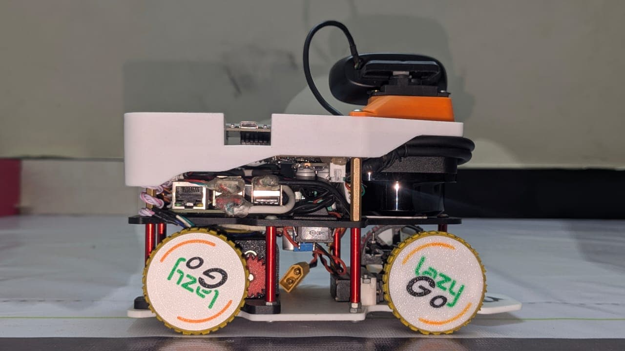
3D preview converted from github.com/A-N-M-Noor/LazyGo_WRO2025 at 643f82a, under MIT. View the original files from GitHub (4.2 MB) (opens in a new tab)
What it can do
Written by Robotheca from the project's documents.
- Autonomously completes three laps on a track in Round 1 using accurate path-following, speed control and lap counting.
- Round 2: avoids green obstacles by moving left and red obstacles by moving right, then parks in a designated zone.
- Real-time odometry combines motor encoder and IMU readings to track the robot's position.
- Tower detection combines LiDAR shape cues with camera color checks.
- Steering uses an Ackermann mechanism driven by a servo; the camera is panned by a servo.
- ROS2 is used for control, split into modular nodes; Gazebo is used for simulation.
- An OLED display on the microcontroller shows sensor readouts, battery warnings and debug info.
Bill of materials
This repository has no parts list Robotheca can read yet.
Build guide
The creator's steps, each with its instructions.
- 1Assemble the first (bottom) layer with motor, steering servo, battery and wheels
- 2Attach standoffs and assemble the second (middle) layer with motor driver, buck
- 3Mount the custom PCB at the top with 30mm standoffs
- 4Connect cables to the PCB using JST connectors
- 5Mount the top cover with pre-installed LiDAR and camera pan servo, and route wir
The guide appears here as you scroll.
Guide by @A-N-M-Noor (README.md), under MIT.
More guides
Wiring and electronics
Notes written by Robotheca from the project's documents.
Main parts
- Raspberry Pi 5 (8GB) for high-level processing with ROS2, vision and LiDAR.
- RPLidar C1 for 360 degree environment scanning.
- Logitech C270 camera for color tower detection.
- ESP32 microcontroller for motor, encoder, IMU, servo and OLED interface.
- 1.3 inch I2C OLED display for status and debugging.
- 25GA gear motors with encoders driving the differential drivetrain.
- VNH2SP30 motor driver for the brushed DC drive motor.
- PS1171MG metal-gear servo for steering and camera pan.
- 5V 20A buck converter powering the Raspberry Pi, LiDAR and ESP32.
- 5V 5A SCT2650 buck converter powering the servo and OLED.
- 3-cell (3S) lithium polymer battery as the main power source.
- Custom through-hole secondary PCB integrating the ESP32, IMU, OLED and power distribution.
Connections
- The 3S battery feeds the VNH2SP30 motor driver directly, which has a built-in regulator for the motor voltage.
- The 20A buck converter (set to 5.1V) supplies the Raspberry Pi 5, RPLidar C1 and ESP32 on a separate ground path from the servo.
- The 5A SCT2650 buck converter is separate so that servo in-rush current does not cause Pi throttling or ESP32 brownout resets.
- Cables between the chassis layers and the PCB are connected with JST connectors.
