Project files
README.md
Machine-translated by Robotheca from the original in Chinese (opens in a new tab). License: MIT (opens in a new tab) and GPL-3.0-only (opens in a new tab).
Making Instructions
The waterproof compartment houses the basic circuitry for the submersible's operation, including 1 C-board, 1 I2C expansion board, 1 PWM expansion board, and the connecting wires for them. The waterproof compartment connects to external circuits via cable-passing screw holes on its back, with the connection corresponding to each screw hole as follows:
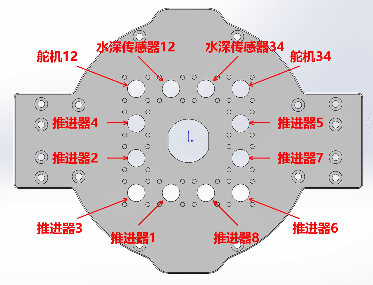
Electronics
The complete wiring diagram for the robot's internal circuitry is shown below:
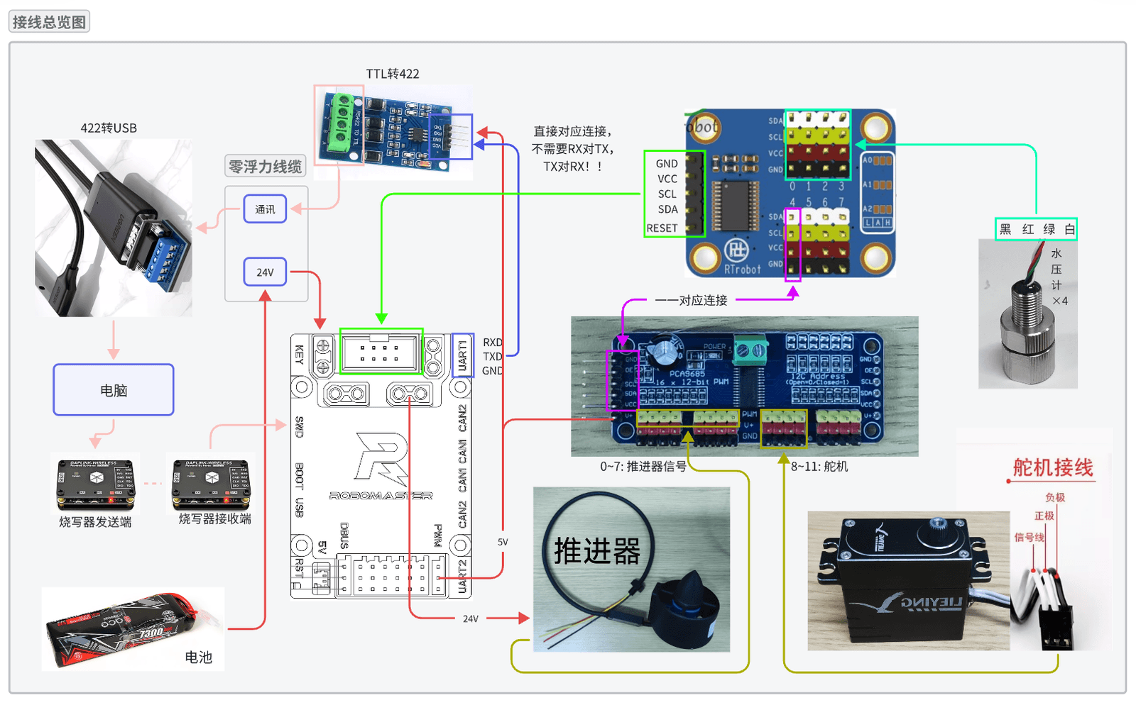
Internal Wiring
C-board to I2C Expansion Board: Pins 2, 4, 6, and 8 of the IIC interface on the C-board are connected to GND, VCC, SCL, and SDA of the input terminal on the I2C expansion board (the side with 5 black base pins arranged in a row), respectively.
C板接IIC扩展板:C板IIC接口的2、4、6、8号分别与IIC扩展板输入端(一侧并排5个黑色底座针脚)的GND、VCC、SCL、SDA相连
I2C Expansion Board to Water Pressure Gauges: The GND, VCC, SCL and SDA of Ports 0 to 3 on the output terminal of the I2C Expansion Board (each port corresponding to 4 base pins of different colors arranged in a row) are connected to the black, red, green and white wires of the 4 water pressure gauges respectively.
IIC扩展板接水压计:IIC扩展板输出端0-3号端口(每个端口对应并排4个底座颜色不同的针脚)的GND、VCC、SCL、SDA分别与4个水压计的黑色、红色、绿色、白色线相连
I2C Expansion Board to PWM Expansion Board: The GND, VCC, SCL and SDA of Port 4 on the output terminal of the I2C Expansion Board are connected to the GND, VCC, SCL and SDA of the input terminal on the PWM Expansion Board (the side with 6 black base pins arranged in a row) respectively.
IIC扩展板接PWM扩展板:IIC扩展板输出端4号端口的GND、VCC、SCL、SDA分别与PWM扩展板输入端(一侧并排6个黑色底座针脚)的GND、VCC、SCL、SDA相连
C-board to PWM Expansion Board: Any 5V port of the PWM interface on the C-board is connected to the V+ of the input terminal on the PWM Expansion Board.
C板接PWM扩展板:C板PWM接口的任意一个5V端口与PWM扩展板输入端的V+相连
Inside/Outside Devices Connection
Manual soldering is overly complex due to numerous wirings, so the following terminal blocks are provided for easy wiring.
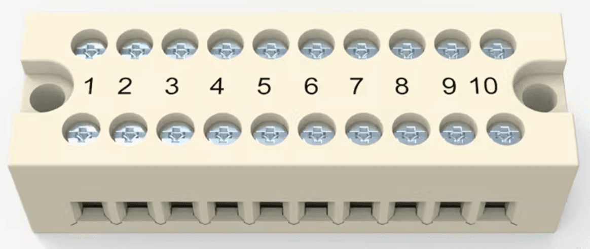
Power Supply to C-board and Propellers: The external battery is connected to the power input port (No.8) of the internal C-board via a power cable, and any of the power output ports (No.9) on the C-board is connected to the power input ports of the 8 propellers (in parallel) through a terminal block.
C-board to Programmer: The wireless programmer is connected to the host computer for firmware programming and debugging. The exterior cabin wireless programmer connects to the interior cabin wireless programmer via the SWD download port on the C‑Board, with SWCLK, SWDIO, GND, and 3.3V pins connected correspondingly.
C-board to Serial Port: The UART6 interface of the C‑Board is connected to the host computer via a TTL‑to‑422 module and a 422‑to‑USB module, for command transmission and reception.
Propellers to PWM Expansion Board: The signal input terminals of the 8 external propellers are connected respectively to the PWM terminals (yellow base pins) of Ports 0 to 7 on the output terminal of the internal PWM Expansion Board.
Servos to PWM Expansion Board: The 4 external servos are connected to Ports 8 to 11 on the output terminal of the internal PWM Expansion Board respectively, with the negative poles connected to GND, the positive poles connected to V+, and the signal wires connected to PWM.
Water Pressure Gauges to Water Pressure Gauge Adapter Boards: The 4 external water pressure gauges connect to the 4 internal water pressure gauge adapter boards, which can be directly inserted into the terminals.
Files by @IWIN-FINS, at commit 1bc38e8, read from GitHub in your browser. Hardware license: MIT; software license: GPL-3.0-only. Robotheca doesn't review code: read it before running it.