EzRover
A cheap, extensible differential drive robot built on an ESP32-CAM, an L9110S motor driver and a Robot Car chassis, with closed-loop speed control, pose estimation and go-to-goal behavior.
- Wheeled
- Open source
- arduino
Suggested by Robotheca, created by @Ezward (opens in a new tab), from github.com/Ezward/Esp32CameraRover2 (opens in a new tab). Pinned to commit a271a99 (opens in a new tab).
- Hardware license
- MIT (opens in a new tab)
- Software license
- MIT (opens in a new tab)
- Commercial use
- Allowed
This repository contains executable files that Robotheca doesn't check. Only run them if you trust the creator.
Photo and 3D model
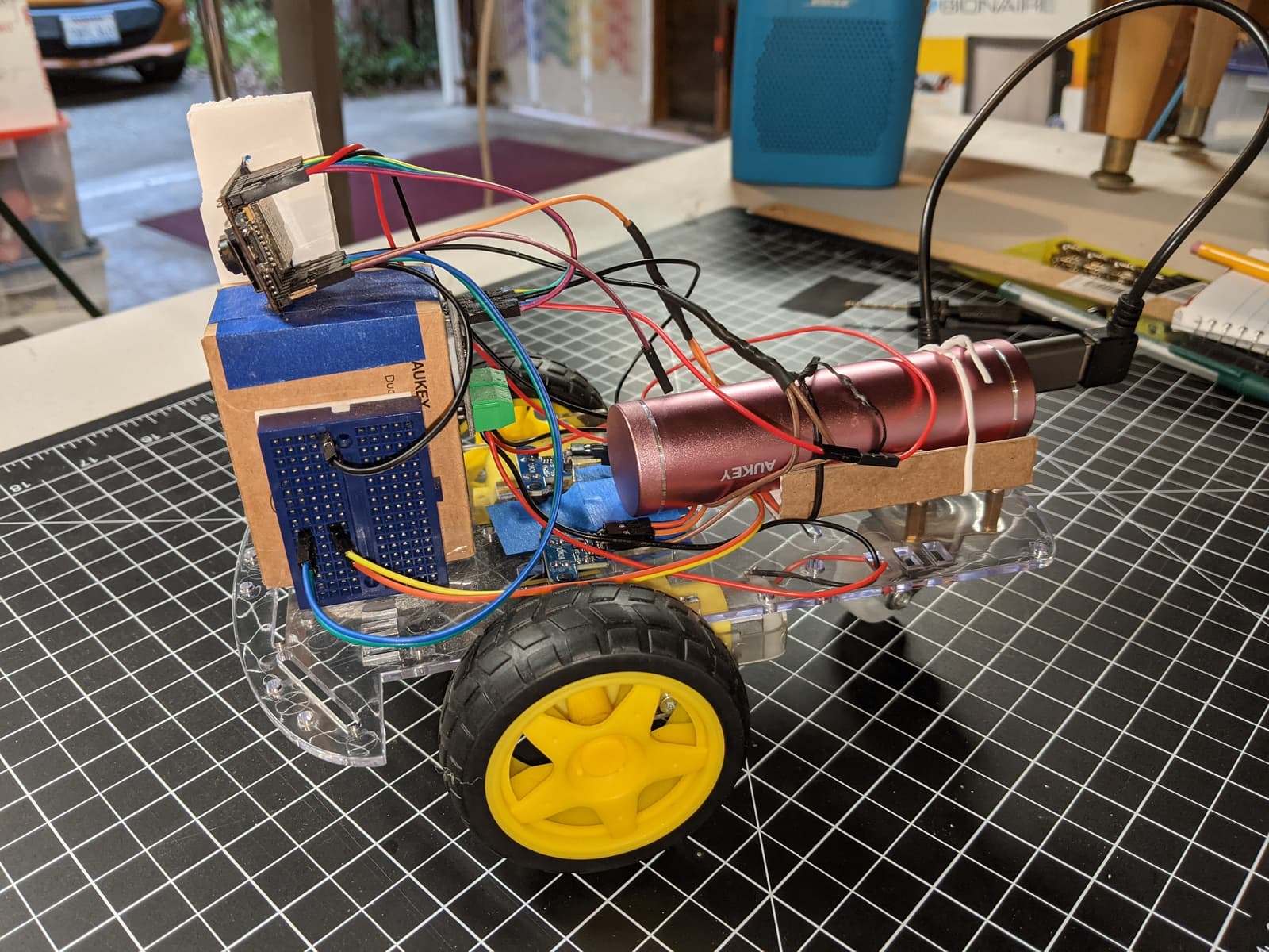
3D preview converted from github.com/Ezward/Esp32CameraRover2 at a271a99, under MIT. View the original files from GitHub (41 KB) (opens in a new tab)
What it can do
Written by Robotheca from the project's documents.
- Drives a differential drive robot with two DC motors, controlled over WiFi by commands from a self-hosted browser application.
- Runs closed-loop speed control of the wheels using wheel encoder feedback.
- Estimates pose from wheel odometry and supports go-to-goal behavior.
- Streams camera video to the browser for first person view teleoperation and telemetry display.
- Can be driven by keyboard, game controller, or algorithmic control from the web application.
- Supports extension in JavaScript with libraries such as OpenCV.js and TensorFlow.js.
Bill of materials
This repository has no parts list Robotheca can read yet.
Build guide
The guide appears here as you scroll.
Guide by @Ezward (README.md), under MIT.
More guides
Wiring and electronics
Notes written by Robotheca from the project's documents.
Main parts
- ESP32-CAM microcontroller board with an OV2640 camera, WiFi and Bluetooth.
- USB to TTL serial converter used to flash firmware and read serial output.
- L9110S dual DC motor driver controlling the two chassis motors.
- Two DC geared motors with wheels on a robot car chassis kit.
- Two LM393 slotted optocoupler modules reading wheel encoder disks.
- Battery supply, a USB battery in the documented wiring, feeding 5V to the board.
Connections
- L9110S motor inputs A1_A, A1_B, B1_A and B1_B connect to ESP32-CAM GPIO 15, 13, 2 and 14.
- Left and right LM393 encoder outputs connect to ESP32-CAM GPIO 3 and GPIO 1 respectively.
- LM393 modules are powered from the ESP32-CAM 3.3V VCC pin so their outputs stay within GPIO tolerance.
- GPIO 1 and GPIO 3 are shared with serial TX and RX, so the encoders and the USB serial converter cannot be connected at the same time.
- Common ground connects the ESP32-CAM, L9110S, LM393 modules and the battery negative terminal.
- Motor wire polarity must be determined by experiment so that the wheels turn forward and backward correctly.
