ESP32 Stepper Self-Balancing Robot
A two-wheeled self-balancing robot built from scratch around an ESP32, an MPU6050 IMU and NEMA 17 stepper motors.
- Other
- Open source
- arduino
- 3D printable
Suggested by Robotheca, created by @FineBeer21 (opens in a new tab), from github.com/FineBeer21/ESP32-self-balancing-robot (opens in a new tab). Pinned to commit a54d175 (opens in a new tab).
- Hardware license
- MIT (opens in a new tab)
- Software license
- MIT (opens in a new tab)
- Commercial use
- Allowed
Photo and 3D model
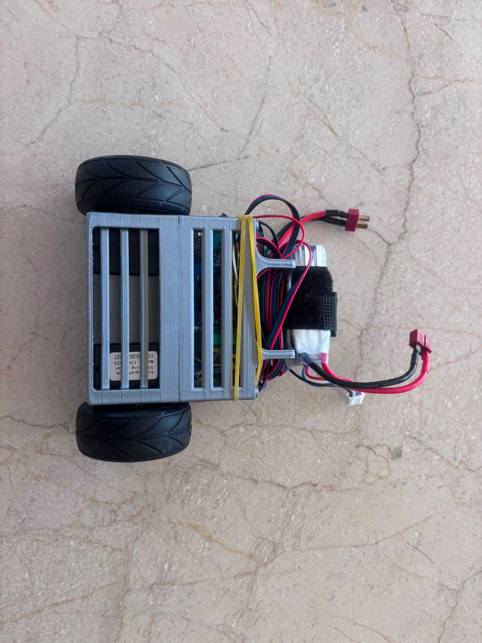
3D preview converted from github.com/FineBeer21/ESP32-self-balancing-robot at a54d175, under MIT. View the original files from GitHub (1.1 MB) (opens in a new tab)
- Power
- 12 V
What it can do
Written by Robotheca from the project's documents.
- Balances as a two-wheeled self-balancing robot using PID feedback from pitch readings.
- Drives its wheels with NEMA 17 stepper motors.
- Uses a custom complementary filter with a negated gyroscope axis to track pitch.
- Stepper step timing is handled by an established stepper library; an earlier custom timer ISR is kept for reference.
- Remote control via Wi-Fi or Bluetooth, forward/backward movement, and yaw steering are planned but not yet implemented.
Bill of materials
This repository has no parts list Robotheca can read yet.
Build guide
The creator's steps, each with its instructions.
- 1Print the chassis parts (base in PETG, upper levels in PLA)
- 2Mount the NEMA 17 stepper motors with cooling cutouts
- 3Hand-solder the wiring on perfboard
- 4Wire the MPU6050 IMU, A4988 drivers and ESP32
- 5Connect the 12V LiPo battery through a buck converter to 5V
- 6Flash the PlatformIO firmware and tune the balancing controller
The guide appears here as you scroll.
Guide by @FineBeer21 (README.md), under MIT.
Wiring and electronics
Notes written by Robotheca from the project's documents.
Main parts
- ESP32 microcontroller.
- MPU6050 inertial measurement unit mounted inverted.
- NEMA 17 stepper motors.
- A4988 stepper motor drivers.
- 12V LiPo battery with a buck converter stepping down to 5V.
Connections
- Hand-soldered point-to-point wiring on perfboard.
- The buck converter steps the 12V battery down to 5V for the logic electronics.
- The README does not give detailed pin or bus connections; see the schematic PDF in the hardware folder.