Endeavor II
A small 3D printed humanoid robot, 50 cm tall and 4 kg, inspired by ROBO-ONE, capable of agile, combat-oriented sequences and dance moves.
- Humanoid
- Open source
- 3D printable
Suggested by Robotheca, created by @ProtoDane (opens in a new tab), from github.com/ProtoDane/EndeavorHumanoid (opens in a new tab). Pinned to commit 505f148 (opens in a new tab).
- Hardware license
- MIT (opens in a new tab)
- Software license
- MIT (opens in a new tab)
- Commercial use
- Allowed
This repository contains executable files that Robotheca doesn't check. Only run them if you trust the creator.
Photo and 3D model
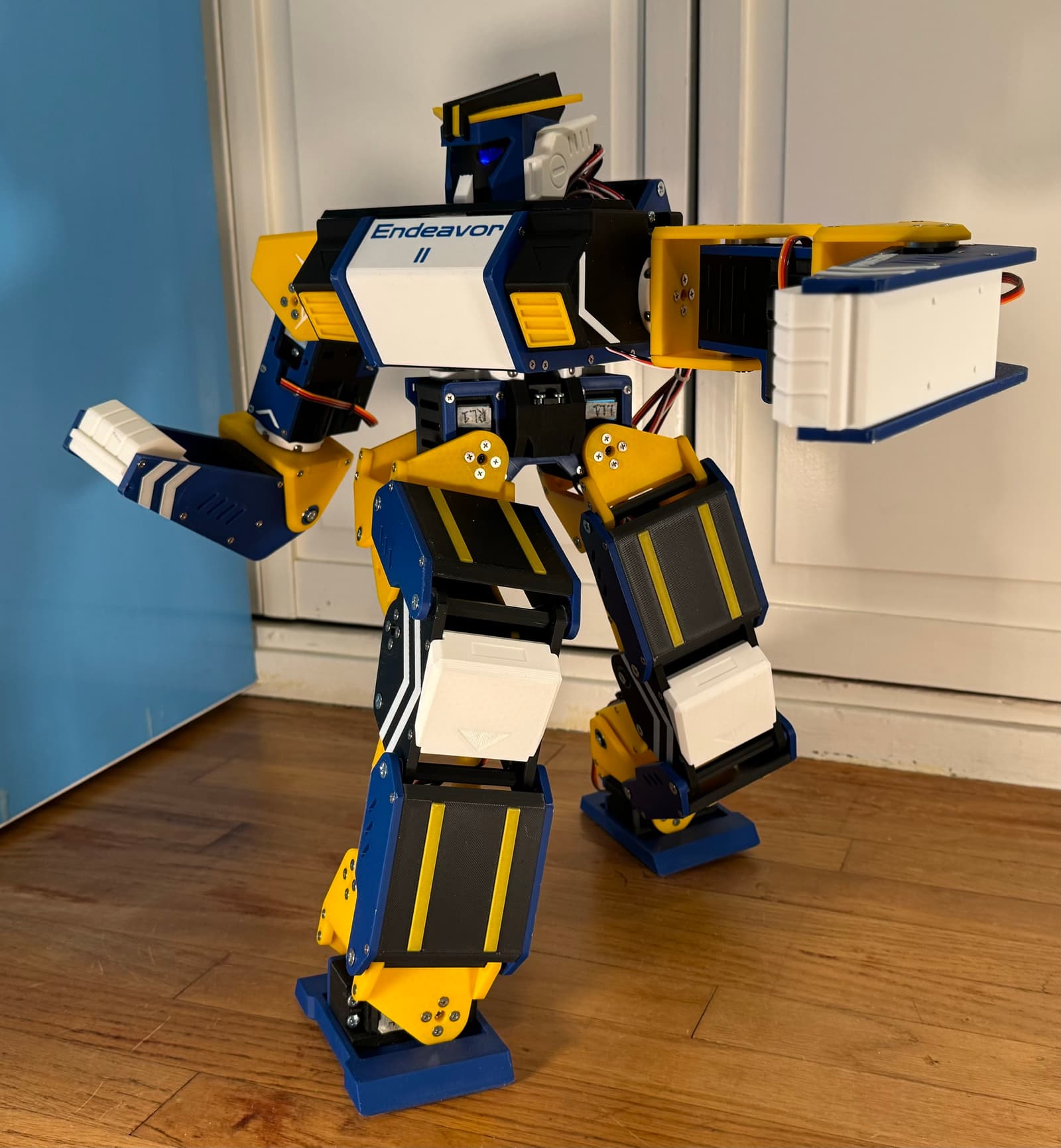
3D preview converted from github.com/ProtoDane/EndeavorHumanoid at 505f148, under MIT. View the original files from GitHub (105 KB) (opens in a new tab)
- Height
- 50 cm
- Weight
- 4 kg
What it can do
Written by Robotheca from the project's documents.
- Designed as a small 50 cm, 4 kg humanoid inspired by ROBO-ONE, capable of agile movements, combat-oriented sequences, and dance moves.
- Servo calibration tool maps intended angles to actual PWM pulse widths in microseconds for each servo.
- Calibration tool works on 180-degree servos; 270-degree servos can be calibrated with adjusted +/-135 degree marks.
Bill of materials
This repository has no parts list Robotheca can read yet.
Build guide
The creator's steps, each with its instructions.
- 1Clone the repository and initialize submodules
- 2Perform servo calibration before assembly
- 3Assemble the hardware following the assembly document
- 4Wire the electronics using the wiring diagram
- 5Set up the software following the software setup document
The guide appears here as you scroll.
Guide by @ProtoDane (README.md), under MIT.
More guides
Wiring and electronics
Notes written by Robotheca from the project's documents.
Main parts
- Commercial off-the-shelf servos, which the robot is built around.
- Arduino board used as the controller for the servo calibration tool.
- External power supply set to servo voltage (typically 7.4 V) for powering the servo during calibration.
- ESP32 controller is mentioned as a planned optimization target in the to-do list.
Connections
- For servo calibration, the servo signal line connects to Arduino pin D7 and the servo ground connects to GND.
- The servo is powered from an external PSU at servo voltage rather than from the Arduino.
- A standard wiring convention is still in progress; the repository points to a wiring diagram image for now.
