CYBERRCORE Self-Driving Car (WRO 2026)
A compact four-wheeled autonomous vehicle for WRO 2026 Future Engineers that uses ESP32-CAM color detection, ultrasonic and gyro sensing, and Ackermann steering to complete open and obstacle rounds.
- Self-driving 1:10
- Open source
- micropython
- 3D printable
Suggested by Robotheca, created by @cyberrcore (opens in a new tab), from github.com/cyberrcore/WRO2026_FE (opens in a new tab). Pinned to commit c2fdba2 (opens in a new tab).
- Hardware license
- MIT (opens in a new tab)
- Software license
- MIT (opens in a new tab)
- Commercial use
- Allowed
Photo and 3D model
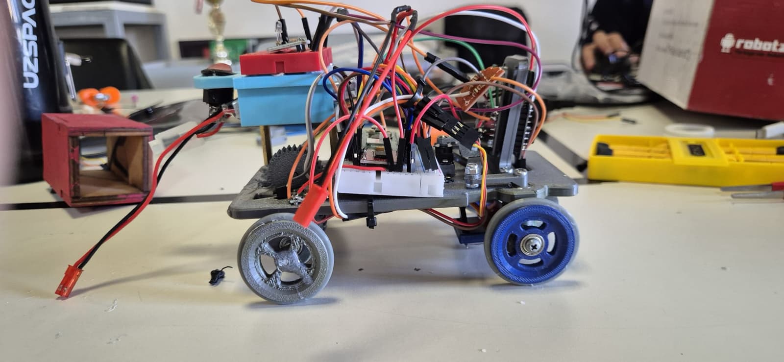
3D preview converted from github.com/cyberrcore/WRO2026_FE at c2fdba2, under MIT. View the original files from GitHub (2.1 MB) (opens in a new tab)
What it can do
Written by Robotheca from the project's documents.
- Autonomous four-wheeled vehicle for WRO 2026 Future Engineers open and obstacle rounds
- Completes 16 corners in the open round using ultrasonic wall detection and gyro-assisted 90 degree turns
- Detects red and green obstacles with a camera and passes them on the right or left respectively
- Stops after a required number of laps (4 in obstacle round) using corner counting
- Steers with a PID heading controller and an Ackermann front steering linkage
- Drive motor controlled by PWM and direction pins through a motor driver
Bill of materials
13 parts13 of 13 parts shown
| # | Component | Quantity | Est. price | Supplier |
|---|---|---|---|---|
| 1 | Raspberry Pi Pico 2 W H | 1 | – | – |
| 2 | ESP32-CAM | 1 | – | – |
| 3 | TB6612FNG | 1 | – | – |
| 4 | 6 V micro DC motor | 1 | – | – |
| 5 | HD-1440A servo | 1 | – | – |
| 6 | US-100 ultrasonic sensor | 1 | – | – |
| 7 | MPU6050 | 1 | – | – |
| 8 | TCS34725 | 1 | – | – |
| 9 | LM2596 / RT3505 buck converter | 2 | – | – |
| 10 | 2S 450 mAh 40C LiPo | 1 | – | – |
| 11 | On/off switch | 1 | – | – |
| 12 | 3x10x4 bearings | 4 | – | – |
| 13 | M3 fasteners / washers | – | – | – |
13 of 13 parts have no price in the source, so there is no parts total. Read from README.md at the pinned commit.
Build guide
The creator's steps, each with its instructions.
- 1Print all custom mechanical parts from models/STL
- 2Assemble main chassis, steering linkage, rear axle, differential, wheel hubs and
- 3Check steering movement manually before installing electronics
- 4Install motor mount, rear gear pair and rear drivetrain
- 5Mount ESP32-CAM and US-100 using printed brackets
- 6Wire electronics according to the electronics wiring scheme
- 7Verify the 5 V logic buck converter output with a multimeter
- 8Verify the 5 V / 6 V servo buck converter output with a multimeter
- 9Confirm all modules share a common ground
- 10Upload camera.cpp to the ESP32-CAM
- 11Copy the selected MicroPython file to the Raspberry Pi Pico
- 12Run servo_tune.py to set center, direction and limits
- 13Run camera_uart_blink.py to test UART communication
- 14Validate open round using openround.py
- 15Validate obstacle round using obstacleround.py
- 16Record final competition videos and place links in video/
The guide appears here as you scroll.
Guide by @cyberrcore (README.md), under MIT.
More guides
Wiring and electronics
Notes written by Robotheca from the project's documents.
Main parts
- Raspberry Pi Pico 2 W H main controller running MicroPython
- ESP32-CAM camera module performing RGB565 color detection
- TB6612FNG motor driver for the brushed DC drive motor
- 6 V micro DC drive motor
- HD-1440A servo for steering
- US-100 ultrasonic distance sensor
- MPU6050 gyro for yaw estimation
- TCS34725 color sensor, described as a backup or future validation module
- Two LM2596 / RT3505 buck converters for logic and servo rails
- 2S 450 mAh 40C LiPo battery with on/off switch
Connections
- ESP32-CAM sends RED, GREEN or NONE lines over UART at 115200 baud to the Pico, with a resistor divider level shift on its TX line
- Pico drives the steering servo with 50 Hz PWM on one GPIO pin
- Pico controls the TB6612FNG with PWM and direction pins, plus a standby pin that must be high to enable output
- MPU6050 and TCS34725 share an I2C bus on the Pico
- US-100 uses separate trigger and echo GPIO pins on the Pico
- Battery feeds one buck converter for the 5 V logic rail, another for the servo rail, and the motor driver's motor supply directly
- All modules share a common ground reference
- Power rails are separated so motor and servo current spikes do not reset the logic boards
