bluecube Line Follower v2
A simple line follower robot built on an ESP32 with two geared N20 encoder motors, a line sensor array, an IR range sensor and an MPU 6050 IMU, designed to compete in Robotic Day.
- Wheeled
- Open source
- 3D printable
Suggested by Robotheca, created by @bluecube (opens in a new tab), from github.com/bluecube/line_follower (opens in a new tab). Pinned to commit e962a7d (opens in a new tab).
- Hardware license
- Unlicense (opens in a new tab)
- Software license
- Unlicense (opens in a new tab)
- Commercial use
- Allowed
This repository contains executable files that Robotheca doesn't check. Only run them if you trust the creator.
Which files (1 script)
Photo and 3D model
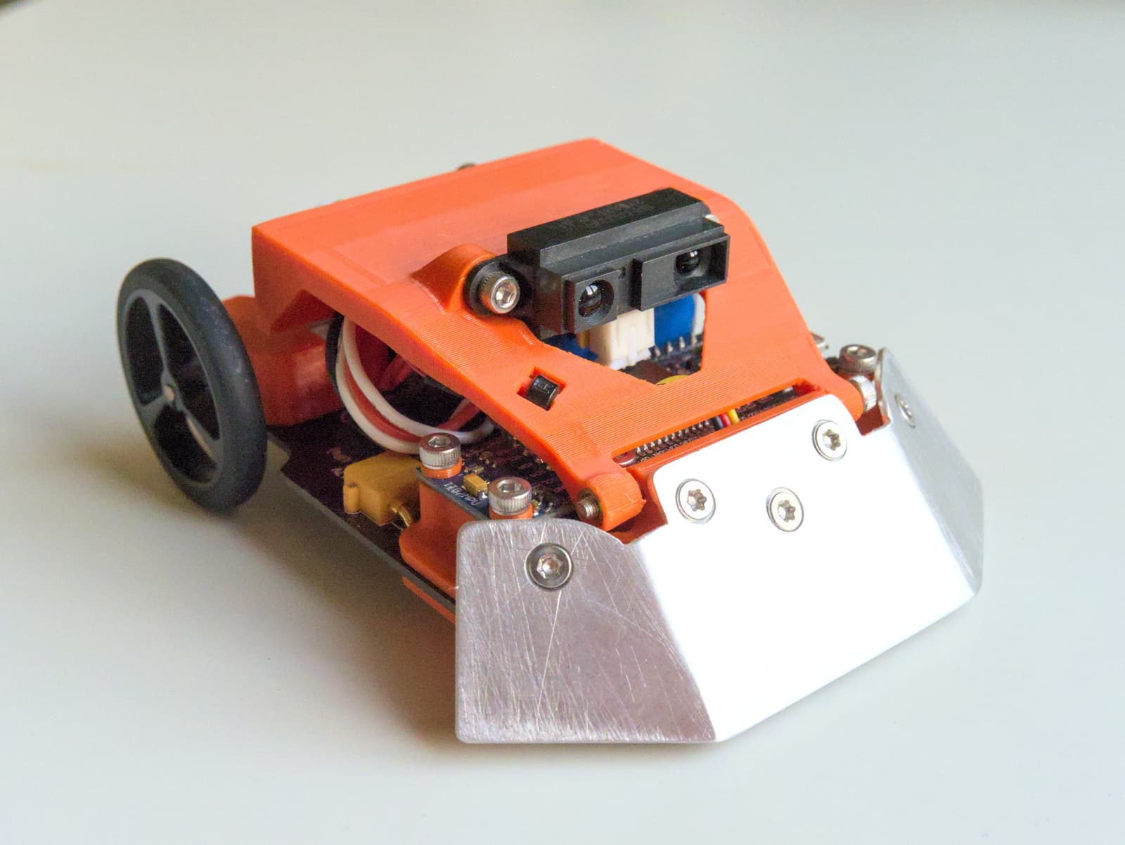
3D preview converted from github.com/bluecube/line_follower at e962a7d, under Unlicense. View the original files from GitHub (1.7 MB) (opens in a new tab)
What it can do
Written by Robotheca from the project's documents.
- Line following on a competition track using a line sensor inspired by PocketBot.
- Uses an IR range sensor to detect obstacles or distance.
- Carries an MPU 6050 accelerometer and gyro for motion sensing.
- Driven by two geared N20 encoder motors with magnetic encoders and Pololu wheels.
- Built as a small robot for the Robotic Day competition, designed for versatile software control.
Bill of materials
This repository has no parts list Robotheca can read yet.
Build guide
The guide appears here as you scroll.
Guide by @bluecube (README.md), under Unlicense.
More guides
Wiring and electronics
Notes written by Robotheca from the project's documents.
Main parts
- ESP32 development board for main computing.
- Line sensor array inspired by Ondrej Stanek's PocketBot design.
- IR distance sensor.
- MPU 6050 breakout board (accelerometer and gyroscope).
- Two N20 DC geared motors with magnetic encoders and Pololu wheels.
- Double sided PCB base (8cm x 10cm) carrying the parts.
Connections
- The main components are mounted on a double sided PCB that serves as the robot base.
- The distance sensor shares GPIO12 with the ESP32 flash strapping pin, which can prevent flashing.
- Fixing this requires permanently setting the ESP32 flash voltage to 3.3V with espefuse, which is irreversible.