Bipedal Self-Balancing Robot
A self-balancing bipedal robot with 2-DOF legs and stepper-driven wheels, built from scratch with an ESP32 controller and dual IMUs.
- Other
- Open source
- arduino
- 3D printable
Suggested by Robotheca, created by @kairobyte (opens in a new tab), from github.com/kairobyte/bipedal_self_balance (opens in a new tab). Pinned to commit 9291561 (opens in a new tab).
- Hardware license
- MIT (opens in a new tab)
- Software license
- MIT (opens in a new tab)
- Commercial use
- Allowed
Photo and 3D model
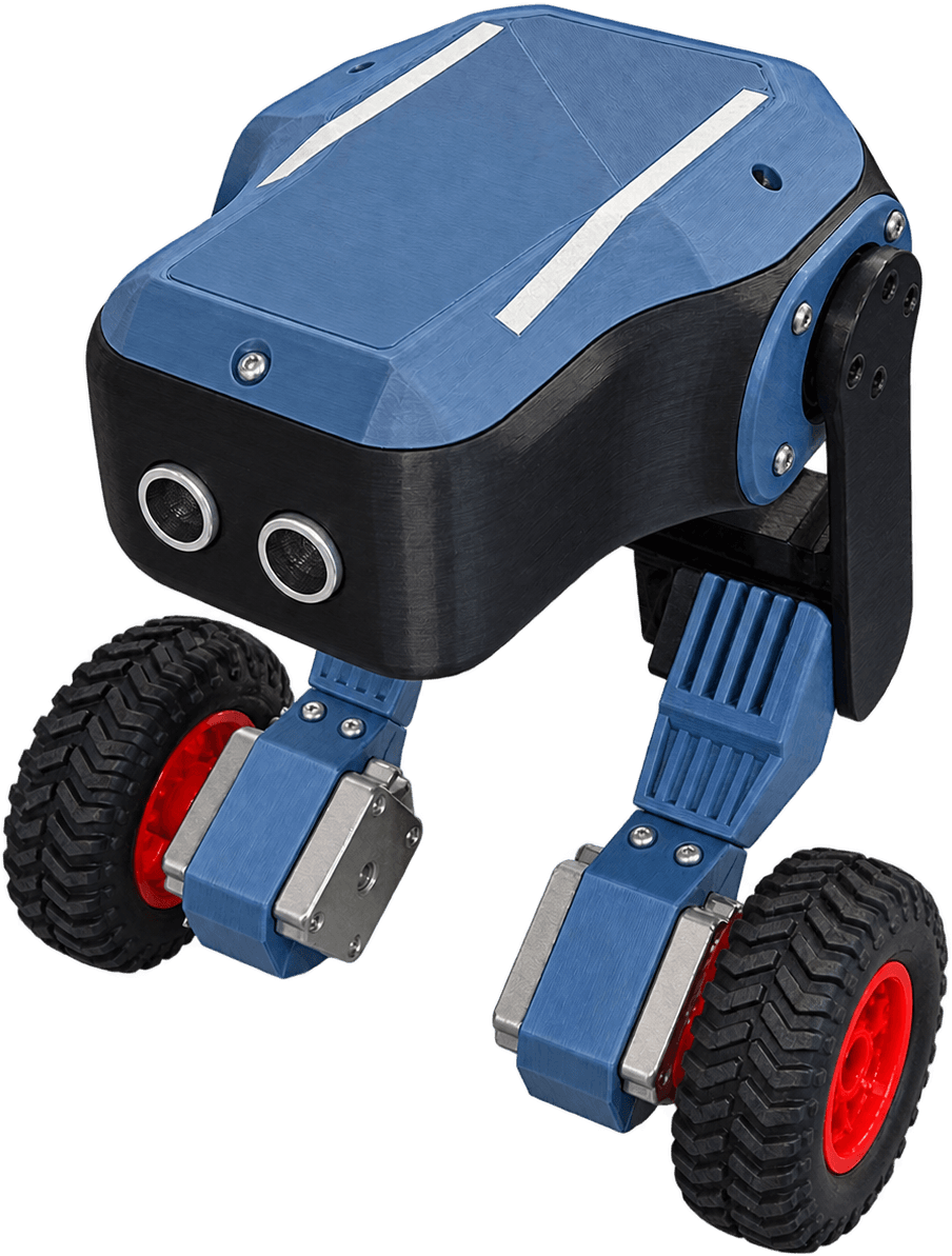
3D preview converted from github.com/kairobyte/bipedal_self_balance at 9291561, under MIT. View the original files from GitHub (7.0 MB) (opens in a new tab)
- Degrees of freedom
- 2
What it can do
Written by Robotheca from the project's documents.
- Balances on two wheels as a self-balancing bipedal robot, currently for only a few seconds at a time.
- Uses PID control running at roughly 1 kHz to keep balance.
- Tuning parameters can be set over serial and saved without reflashing the ESP32.
- Legs have 2 degrees of freedom for lean control.
- Planned: PS4 controller support over Bluetooth and possible machine learning-based balancing.
Bill of materials
This repository has no parts list Robotheca can read yet.
Build guide
The creator's steps, each with its instructions.
- 1Model the parts in SolidWorks, building bottom-up from stepper holders to legs t
- 2Design the PCB schematic and layout, run DRC, and export Gerber files
- 33D print the parts and arrange them in the slicer
- 4Assemble the 3D printed parts and complete the wiring
- 5Flash the test code to confirm motors, sensors and RGB indicators work
- 6Tune the PID controller over serial until the robot balances
The guide appears here as you scroll.
Guide by @kairobyte (README.md), under MIT.
Wiring and electronics
Notes written by Robotheca from the project's documents.
Main parts
- ESP32 as the main controller.
- Dual IMUs, MPU6050 and MPU9250, for sensor redundancy.
- A4988 stepper drivers controlling stepper motors that drive the wheels.
- Servos for the legs.
- Two buck converters stepping down 12V from a 3S LiPo battery, one for sensors and one for servos.
- A capacitor and diode to protect the ESP32 from brownouts.
Connections
- Two buck converters split power: one dedicated to sensors and one to servos, keeping noisy current away from sensor power.
- A capacitor and diode are placed to guard the ESP32 against brownouts during high servo and stepper current draw.
- Extra wires for the second leg degree of freedom were soldered directly onto the ESP32.
