Project files
README.md
Machine-translated by Robotheca from the original in Chinese (opens in a new tab). License: Apache-2.0 (opens in a new tab).
BalanceBall Spherical Version
BalanceBall
——by sytnocui 2023/8/31 v1.0
Bilibili video link: TODO
0. A Tragic Past
If you participated in the 2021 National Undergraduate Electronic Design Contest, you must know that the bill of materials included acrylic balls. At the time, everyone guessed the theme was spherical robots, and suddenly, videos of spherical robots flooded Bilibili. We even stocked up on a bunch of acrylic balls, spending at least 200 yuan just to buy the balls. However, due to reasons like the pandemic delaying the competition, the final control task turned out to be a hospital logistics cart unrelated to acrylic balls. While we were devastated, the problem of what to do with the leftover acrylic balls became an issue.
Acrylic balls are unsellable, save us!!!
1. Project Description
This project aims to create a spherical version of the balancing cube. The overall architecture uses three brushless motors to drive three orthogonally mounted flywheels, with the entire sphere resting on a chassis composed of three omni wheels. Omni wheels allow movement in both the forward direction and the axial direction, so a chassis made of three omni wheels enables the balancing sphere to perform three-degree-of-freedom omnidirectional attitude maneuvers. The sphere on the omni-wheel chassis achieves omnidirectional attitude maneuvers by utilizing the principle of conservation of angular momentum.
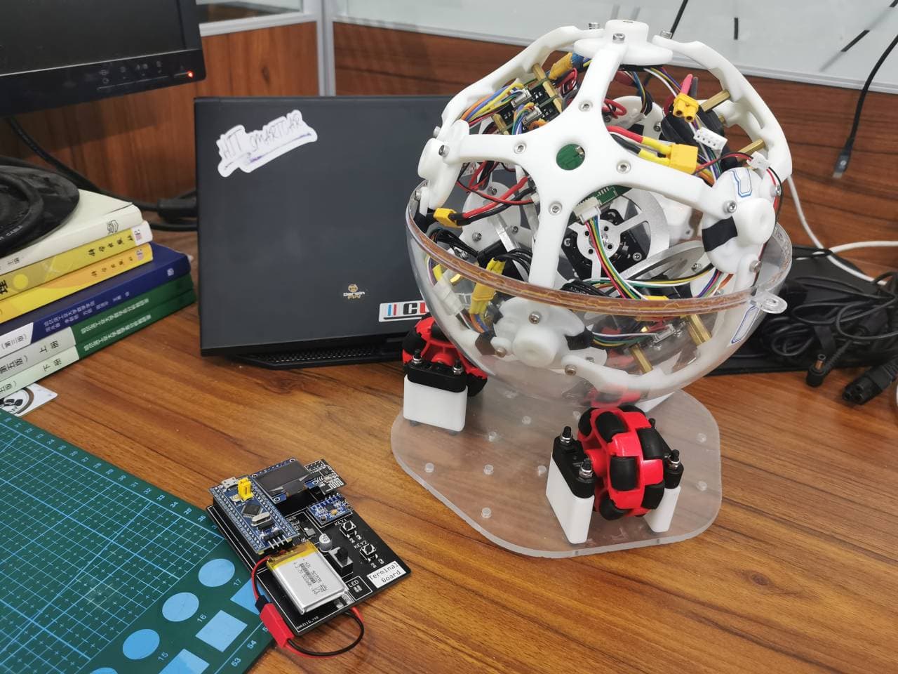
Here's another SolidWorks exploded rendering:

2. Open Source License
This project is licensed under the Apache 2.0 license. Please cite the source when reusing.
3. Project Attributes
This project is being publicly released for the first time and is an original work by the author. The project has not won any awards in other competitions.
Additionally, this project is also part of the author's senior-year innovation and entrepreneurship project, which has not yet been completed. Whether it will be passed on to junior students for future competitions remains to be discussed.
4. Related Features and Physical Demonstrations
-
Full-attitude free rotation of the balancing ball
-
Three-axis angular velocity closed-loop control and power-assisted mode for the balancing ball
-
Three-axis attitude tracking and follow-up for the balancing ball (requires a terminal to complete)
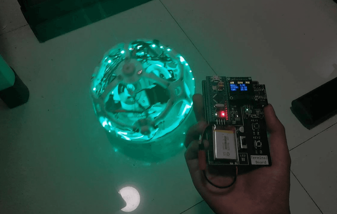
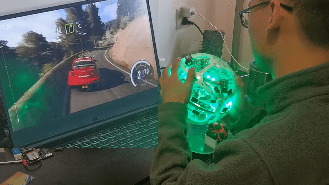
- Real-time broadcasting of the balancing ball's three-axis attitude, capable of mimicking the steering wheel from The Wandering Earth for playing various racing games
5. Design Principles
The project can be divided into three main parts: structural design, hardware design, and software design.
5.1 Structural Design
The structural design concept of this project draws heavily from the classic balancing cube in Zurich:

As shown in the diagram, the balancing cube has six faces, which can be divided into the top three faces and the bottom three faces based on their distance from the ground. It is clearly visible that the three orthogonal flywheels are mounted on the bottom three faces, while the battery, circuit board, and other components are installed on the top three faces.
Based on the principles of solid geometry, it is natural to think that a cube has a circumscribed sphere. By taking the circumscribed sphere of the balancing cube and projecting all six faces outward onto this sphere, we obtain our balancing sphere.
The 3D model built according to this concept is as follows:

5.2 Hardware Design
This project includes a main control board, FOC driver board, encoder board, and gyroscope board. The hardware topology diagram of the project is as follows:

Details:
- The main control board and FOC driver boards are all powered in a cascaded manner and also transmit target commands via the CAN bus.
- There are three FOC driver boards, each connected to an encoder board to obtain the position of the brushless motor and drive a brushless motor.
- The main control board is connected to a gyroscope board to read attitude information in real time.
- The main control board is connected to an ESP8266 communication module.
5.2.1 Main Control Board
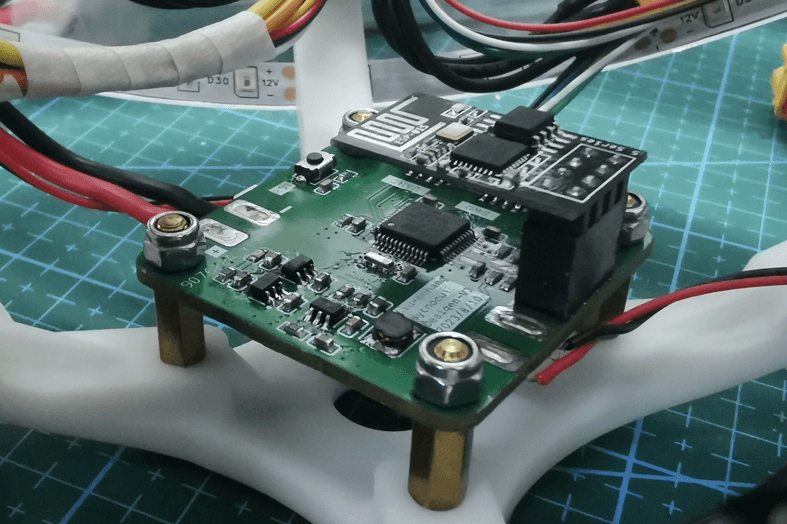
The main control board is a four-layer PCB that can be printed for free via JLCPCB. Its primary functions include Wi-Fi wireless communication, reading gyroscope posture, posture resolution, control mode management, and running control algorithms.
-
Main controller: STM32F103C8T6
-
Oscillator: Murata ceramic three-pin oscillator CSTCE 8M (same as used in Zhi Hui Jun's robotic arm; no load capacitors required)
-
CAN communication chip: TJA1050T (Note: requires 5V power supply; otherwise, the MCU CAN transceiver will freeze)
-
Power management: JW5026 + ME6211
-
Wireless communication: Classic pin-type ESP8266 wireless communication module
-
All connectors used are of the GH1.25 type;
All components can be purchased on Taobao, with an estimated cost of around 30 RMB per set (prices of electronic components may vary).
Compatible encoder boards include: ICM20602, MPU6050, ICM42688P (currently problematic, severe overheating; please use the ICM20602 module instead)
Note: The encoder board is fixed with hot melt adhesive at the topmost point inside the ball, parallel to the ground.
5.2.2 Driver Board
The driver board is a four-layer PCB that can be printed for free via JLCPCB. The driver board mainly completes FOC closed-loop speed control.
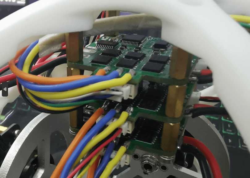
The driver board design references the Lemon FOC open-source board and is based on the GD32 series.
The hardware of the driver board is independently designed, while the software is directly flashed with Lemon FOC's code. The original open-source project allows setting current closed-loop, speed and position closed-loop modes via a PuTTY serial port assistant. However, for this project, a speed step-change mode is adopted.
When using the original firmware, modify the undervoltage protection and speed protection parameters in the serial port debugging assistant to prevent motor stalling due to sudden speed changes.
Driver board parameters:
- Main control: GD32C103CBT6
- Oscillator: Murata CSTCE 8M ceramic three-pin oscillator
- CAN communication chip: SN65HVD232D
- Power management: JW5026 + RT9013-3.3
- Motor driver chip: FD6288T (motor driver chip + MOSFET, high-current solution)
- NMOS: TPH1R403NL
- Current sampling: LMV358IPWRG4 (low-bias sampling)
- Sampling resistor: 1206 1mR
- All connectors used are GH1.25 type
- Compatible encoder: MT6816 (must purchase the SPI mode version, easy to buy the wrong one, so be careful)
All components can be purchased on Taobao, with an estimated total cost of around 60 RMB per set (electronic component prices may vary).
5.3.3 BIG Handheld Terminal
The BIG handheld terminal is a two-layer board that can be printed for free by JLCPCB. The BIG handheld terminal mainly completes functions such as remotely changing control modes, safety management, real-time status display, and publishing target poses.
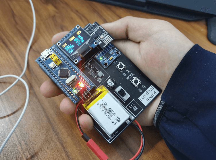
This module is benchmarked against the PICO terminal design by Zhihui Jun, mainly completing some human-computer interaction functions. Since it is aimed at beginners, it looks quite rough. Because PICO means small, Zhihui Jun's PICO is indeed very small, but my handheld terminal is very large, so it is named BIG.
The parameters of the handheld terminal are as follows:
- Main control: STM32F103C8T6 Bluepill core board
- Display: 7-pin OLED display, SPI mode
- Battery: 1s lithium battery 300mAh
- Gyroscope: Classic MPU6050 module
- Wireless communication: Classic pin-type ESP8266 wireless communication module
5.3 Software Design
5.3.1 Full-Attitude Drag Effect
This is implemented on the main control board using the Mahony attitude estimation method to derive real-time roll, pitch, and yaw angles. A separate PID feedback loop is established for each axis. Whenever angular velocity is detected on any axis, the PID algorithm generates a control output in the opposite direction on that axis. The three PID outputs are then summed, left-multiplied by the speed allocation matrix, and converted into target speeds for the three orthogonally mounted flywheels. These speeds are sent to the FOC driver board, producing a drag effect during the ball’s three-degree-of-freedom full-attitude motion.
5.3.2 3-Axis Attitude Tracking Follow-up
Building on the content from Section 5.3.1, attitude angle feedback is added. The BIG handheld terminal collects its own attitude as the target value for the balancing ball's attitude. The difference between the target and the actual attitude of the balancing ball forms a PID controller. This ultimately achieves 3-axis attitude tracking follow-up.
Since the omnidirectional wheel chassis introduces significant friction to the system, this feature currently requires placing the ball directly on the ground rather than on the omnidirectional wheel chassis.
Considering the limitations of pure PID control, future work in this project will involve deploying and comparing additional control algorithms such as LQR.
5.3.3 Playing racing games as a steering wheel
We accidentally discovered that our ball is very similar to the spherical steering wheel in The Wandering Earth. By connecting the ball to a computer via a Wi-Fi module, we receive real-time attitude information from the spherical simulator and map it to virtual Xbox gamepad joystick values (steering wheel, throttle, brake, etc.) using Python's vgamepad library. This allows the virtual game joystick to be recognized in racing games like Dust Rally 2.0, thereby obtaining control data.
Since the control data is encapsulated in the form of an Xbox controller, there are no compatibility issues when playing any racing game.

6. Notes
6.1 Software Description
This project provides firmware code for the main control board and the BIG handheld terminal. The firmware for the driver board is identical to LemonFOC, and its burning and usage should also follow the LemonFOC project:
Reference link: Happy New Year LemonFOC Open Source Board - JLCPCB EDA Open Hardware Platform (oshwhub.com) (opens in a new tab)
All microcontroller firmware in this project is developed using CLion. If you are unfamiliar with CLion project configuration, it is recommended to watch Zhi Hui Jun's guide on configuring CLion for STM32 development:
Reference link: Configuring CLion for STM32 Development | Elegant Embedded Development - Zhihu (zhihu.com) (opens in a new tab)
6.2 Motor Selection
Selecting the right motors for the flywheel and brushless motors is crucial. Given the high friction in the entire system, the low-kV gimbal motors commonly used in the open-source community, such as those in the Lelo Triangle and Balance Cube projects, often fail to meet torque requirements. While browsing second-hand motors on Taobao, I came across this motor:
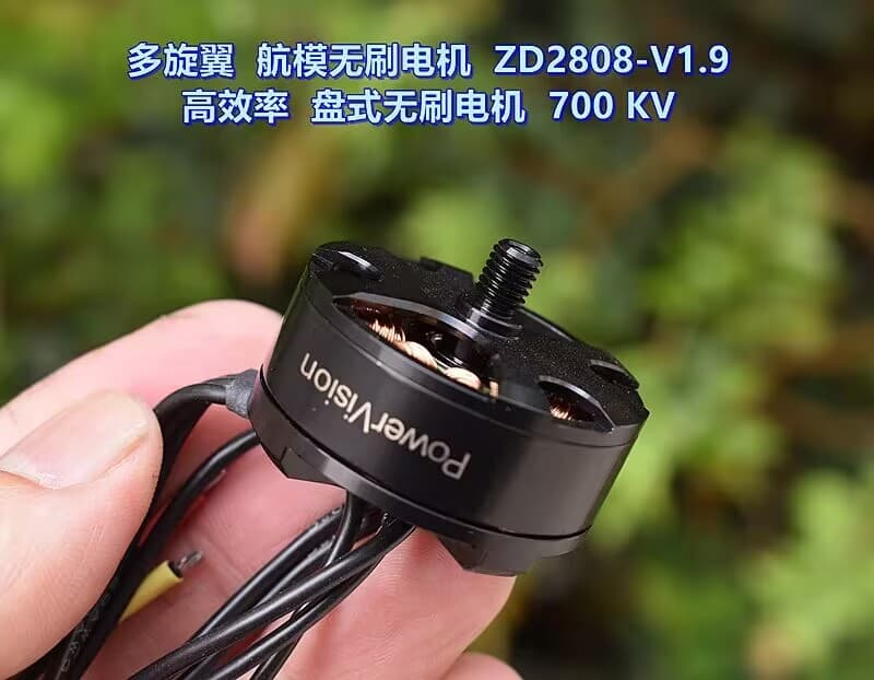
After testing, this motor proved to be well-suited for this project in terms of load capacity, is cost-effective (only 16 yuan), and space-efficient. Considering that such second-hand motors often sell out quickly, if this motor becomes unavailable in the future, the DJI 2312 Phantom motor can be considered as a replacement.
Additionally, if the aluminum alloy flywheel cannot provide sufficient reaction torque, you can follow the solution from this open-source project: fabricate a flywheel and drill holes along the outer edge to install bolts, thereby increasing the flywheel's rotational inertia.

Reference: Self-balancing Lelo Triangle based on LQR controller (Bilibili) (opens in a new tab)
6.3 Gyroscope Selection
The gyroscope board used in this project is the ICM42688P. However, different batches of ICM42688P purchased from Taobao all exhibited issues such as correct data readings but severe heating (around 60°C) and significant temperature drift. It has been confirmed that the problem is not related to soldering; the cause might be material defects or hardware design flaws. It is recommended to exercise caution when purchasing ICM42688P from Taobao. In this project, the ICM20602 module from Zhufly Technology is temporarily used as the gyroscope board.
Currently, the project uses the ICM20602 module "borrowed" from the club. Additionally, the main control board supports an MPU6050 plug-in. The driver code for all three gyroscopes is included in the project, but the interface code needs to be modified manually.
8. Project Progress
First open-source release: August 30, 2023
Completed parts of the project:
- All structural and hardware design and assembly have been completed; the structural and hardware design has matured.
- All logical code has been written.
- Basic control algorithms have been implemented, enabling fundamental angular velocity closed-loop and attitude closed-loop control.
Future plans for the project:
- Due to the complexity of the control system, subsequent work will focus on optimizing the attitude closed-loop control code, with the following measures:
- Adding counterweights to center the center of gravity and equalize the three-axis inertia.
- Replacing PID with model-based control algorithms, such as those based on Euler equations or LQR modeling.
- Performing parameter identification for friction and compensating it using a disturbance observer (or using ADRC algorithms).
- Attempting attitude closed-loop control based on quaternions to eliminate Euler angle gimbal lock issues.
- Project members are independently developing FOC driver code based on the STM32F103C8T6. Once completed, this will replace the current GD32-based driver board from Lemon FOC.
- A Qt and OpenGL-based upper computer software will be developed for real-time attitude visualization and remote parameter tuning, with reference to the effect of Zhi Hui Jun's electronic robots and various flight control debugging assistants.
- An embedded shell will be implemented to support remote parameter tuning via Wi-Fi serial port.
- Shock-absorbing pads will be added to the gyroscope to prevent high-frequency motor vibrations from interfering with the gyroscope.
- Issues with the ICM42688P will be identified and replaced with the currently used ICM20602.
9. Material Description
BOM for structural components:
| Material | Purpose | Quantity | Purchase Link |
|---|---|---|---|
| Main Ball Structure | |||
| 20 mm acrylic shell | Transparent outer shell | >=2 | https://m.tb.cn/h.54hODsa?tk=Q7ZXdzW9Ydo (opens in a new tab) |
| 3D printed (internal support frame - dot connection) | Cross-shaped main frame | 6 | JLC3DP (3D Monkey) |
| 3D printed (internal support frame - bridge point) | Connection points for main frame | 8 | JLC3DP (3D Monkey) |
| 3D printed (small battery bracket) | Battery mount | 1 | JLC3DP (3D Monkey) |
| Brushless Motor Related | |||
| Pancake brushless motor ZD2808-V1.9 | 3 | https://m.tb.cn/h.5WJTsy4?tk=4qczdC51605 (opens in a new tab) | |
| 6 mm x 80 mm aluminum flywheel | 3 | https://m.tb.cn/h.5e1xS1N?tk=HlGCdC6gCA1 (opens in a new tab) | |
| 6 x 2.5 mm radial magnet | Motor shaft position sensing | 3 | https://m.tb.cn/h.54hiYKJ?tk=QM5mdzWTh2m (opens in a new tab) |
| 3M Super Glue | Attach magnets to motor shaft | 1 | https://m.tb.cn/h.54AlcCb?tk=jlEVdzWQEFG (opens in a new tab) |
| Ball Accessories | |||
| M3 x 8 cup head screw | Main structural screws | Several | |
| M3 lock nut | Main structural nuts | Several | |
| M3 x 10+6 copper pillar | Main support pillars | 20 | |
| M3 x 5 x 5 embedded nut | Connect shell to 3D printed parts | 2 | |
| M3 x 8 countersunk screw | Connect shell to 3D printed parts | 2 | |
| Counterweight | Balance center of gravity | Several | https://m.tb.cn/h.56VXPSI?tk=n4DUWYhMTac (opens in a new tab) |
| Electronics | |||
| Main control board | 1 | JLCPCB free PCB, components to be sourced | |
| FOC driver board | 3 | JLCPCB free PCB, components to be sourced | |
| Encoder board | 3 | JLCPCB free PCB, components to be sourced | |
| Gyroscope board (optional) | 1 | JLCPCB free PCB, components to be sourced | |
| BIG handheld terminal | 1 | JLCPCB free PCB, components to be sourced | |
| WiFi module | Communication between ball, BIG, and PC | 3 | https://m.tb.cn/h.56vZKps?tk=XmldWYhGjPn (opens in a new tab) |
| USB-to-serial module for PC | Communication with PC | 1 | https://m.tb.cn/h.56vZKps?tk=XmldWYhGjPn (opens in a new tab) |
| 3S 550 mAh 85C LiPo battery | Power supply | >=1 | https://m.tb.cn/h.5fuIsF0?tk=Pxn2dzWQvsg (opens in a new tab) |
| Wiring | |||
| 18 AWG silicone wire | Power lines | Several | |
| 20 AWG silicone wire | Motor lines | Several | |
| GH1.25 6P double-ended reverse 30 cm | Encoder wires | 3 | |
| GH1.25 6P double-ended reverse 30 cm | Gyroscope wires | 1 | |
| GH1.25 2P double-ended reverse 15 cm | CAN bus wires | 4 | |
| XT30 connector | Battery connection | 1 | |
| Chassis | |||
| Acrylic cut (top chassis) | Main chassis | 1 | Custom acrylic cutting service |
| 3D printed (omni-wheel shaft seat - key) | Omni-wheel support | 3 | JLC3DP (3D Monkey) |
| 3D printed (omni-wheel shaft seat - round) | Omni-wheel support | 3 | JLC3DP (3D Monkey) |
| 3D printed (omni-wheel support leg - split) | Omni-wheel support | 6 | JLC3DP (3D Monkey) |
| RC car omni-wheel | Support acrylic shell | 3 | https://m.tb.cn/h.5Vqiebu?tk=y4CAdzW76o4 (opens in a new tab) |
| 7 x 11 x 3 bearing | Connect omni-wheel and linear shaft | 6 | https://m.tb.cn/h.54hQEqA?tk=cFWBdzW7L1a (opens in a new tab) |
| Linear shaft cut (omni-wheel shaft) | Support omni-wheel, slot required | 3 | https://m.tb.cn/h.5fuKVfU?tk=G4sGdzW7mtl (opens in a new tab) |
| M4 x 55 screw | Secure omni-wheel shaft seat | 12 | |
| M4 lock nut | Secure omni-wheel shaft seat | 12 | |
| Foot pad (optional) | Anti-slip base | Several | https://m.tb.cn/h.54AknHL?tk=cSfIdzWjeUe (opens in a new tab) |
The total cost is around 800–1,000 RMB. Prices for some components fluctuate significantly; please refer to actual quotes.
Files by @sytnocui, at commit 411e3fe, read from GitHub in your browser. Hardware license: Apache-2.0; software license: Apache-2.0. Robotheca doesn't review code: read it before running it.