Antagonistic Tendon Driven Continuum Robot
A research continuum robot with 4 degrees of freedom that drives two tendons per antagonistic pair with a single servo and measures tendon force with load cells.
- Other
- Open source
- ROS
- 3D printable
Suggested by Robotheca, created by @ChristianMarzi (opens in a new tab), from github.com/ChristianMarzi/Tendon-Driven-Continuum-Robot (opens in a new tab). Pinned to commit b399713 (opens in a new tab).
- Hardware license
- CERN-OHL-W-2.0 (opens in a new tab)
- Software license
- CERN-OHL-W-2.0 (opens in a new tab)
- Commercial use
- Allowed
Photo and 3D model
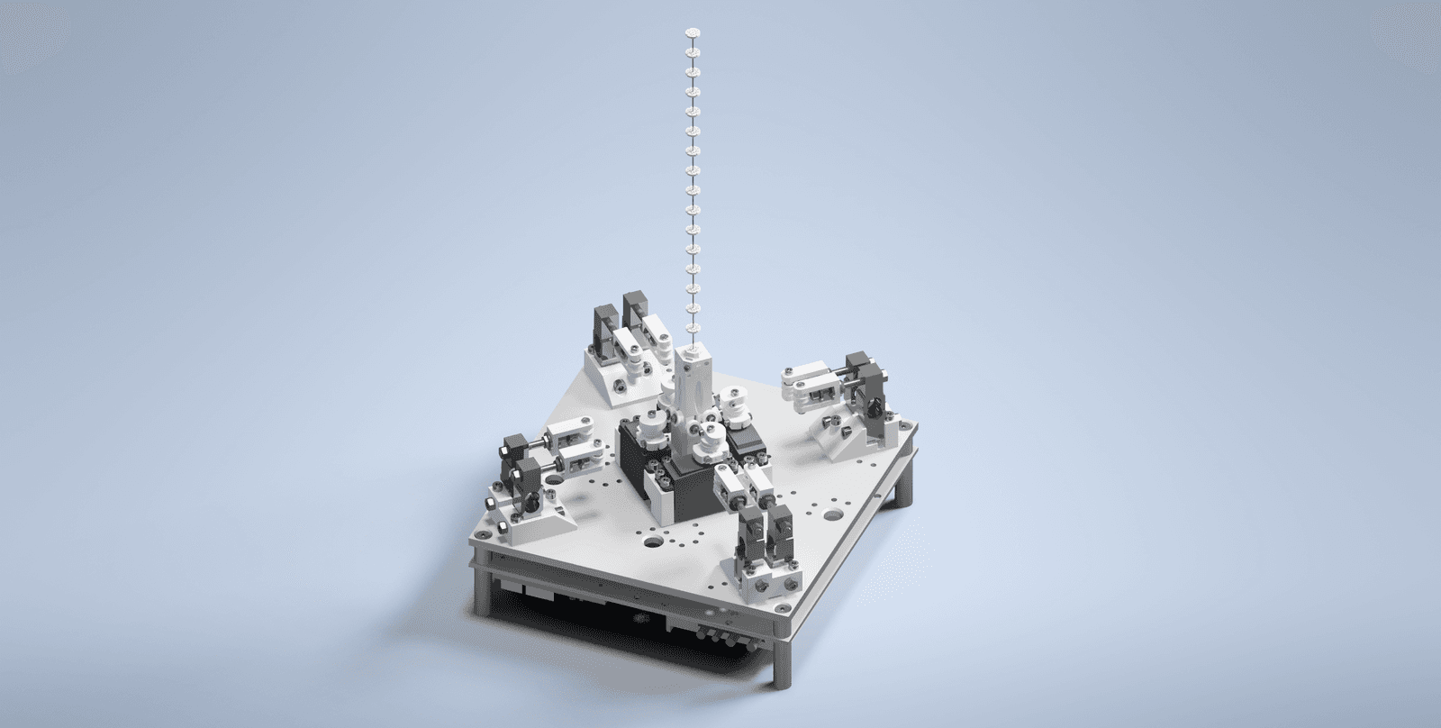
3D preview converted from github.com/ChristianMarzi/Tendon-Driven-Continuum-Robot at b399713, under CERN-OHL-W-2.0. View the original files from GitHub (3.6 MB) (opens in a new tab)
- Degrees of freedom
- 4
What it can do
Written by Robotheca from the project's documents.
- Drives a 4-DOF antagonistic tendon-driven continuum robot research platform
- Each tendon pair is actuated by a single servo motor
- Measures tendon force through load cells routed in the tendons
- Motor positions are set by incoming messages on one topic per motor, via ROS
Bill of materials
This repository has no parts list Robotheca can read yet.
Build guide
The creator's steps, each with its instructions.
- 1Print the substruction, base, force measurement and robot body parts
- 2Assemble the power supply, Arduino and load cell measurement hardware in the sub
- 3Mount the servo motors, tendon pulleys and base plate
- 4Assemble the force measurement mounts, load cells and tensioning mechanism
- 5Build the robot body from the Nitinol backbone and spacer disks
- 6Flash the motor driver firmware to the Arduino and set up rosserial
- 7Connect the Phidget 4-Input Bridges and the ROS load cell driver
The guide appears here as you scroll.
Guide by @ChristianMarzi (README.md), under CERN-OHL-W-2.0.
Wiring and electronics
Notes written by Robotheca from the project's documents.
Main parts
- Arduino Uno controller running the servo firmware
- SunFounder SF3218MG 20 kg high-torque servo motors
- 5 kg TAL220B load cells for tendon force measurement
- Phidget 4-Input Bridges digitize the load cell values
- Power supply housed in the substructure module
Connections
- Load cells are read through Phidget 4-Input Bridges, which publish values to individual ROS topics
- Servo motors are driven from the Arduino Uno, which connects to the ROS network via rosserial
- Power supply, Arduino and load cell measurement hardware are grouped in the substructure module