AIRA
A 3D-printable 7-DoF robotic arm with native LeRobot integration for teleoperation, demonstration recording, and policy training.
- Robot arm
- Open source
- Works with AI
- LeRobot
- 3D printable
Suggested by Robotheca, created by @robertorobotics (opens in a new tab), from github.com/robertorobotics/Nextis-AIRA-3D (opens in a new tab). Pinned to commit 840f8f4 (opens in a new tab).
- Hardware license
- Apache-2.0 (opens in a new tab)
- Software license
- Apache-2.0 (opens in a new tab)
- Commercial use
- Allowed
Photo and 3D model
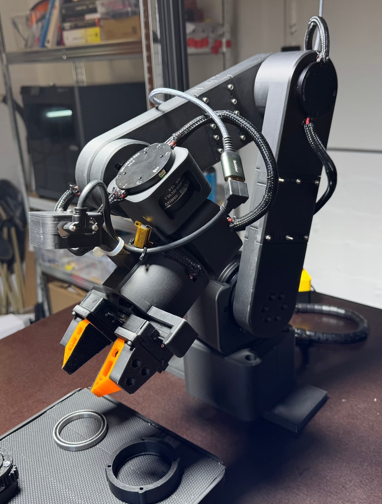
3D preview converted from github.com/robertorobotics/Nextis-AIRA-3D at 840f8f4, under Apache-2.0. View the original files from GitHub (4.2 MB) (opens in a new tab)
- Degrees of freedom
- 7
What it can do
Written by Robotheca from the project's documents.
- Works as a 7-DoF robotic arm: six joints plus a one-DoF gripper, built to be 3D printed.
- Supports teleoperation with a leader arm that drives the follower arm.
- Records demonstrations and trains or runs learned policies through the LeRobot framework.
- Follower arm uses Damiao CAN bus motors with MIT impedance control for compliant position tracking.
- Interactive setup wizard configures each motor's IDs and calibration.
- Optional wrist camera (RealSense D405) is supported.
Works with AI
Found by Robotheca in the project's files at commit 840f8f4, its robot.yaml and Robotheca's notes on its documents. Never guessed; Robotheca doesn't run the code.
Runs LeRobot
Stated in robot.yamlHas LeRobot code
In the project files: src/lerobot_robot_aira“Records demonstrations and trains or runs learned policies through the LeRobot framework.”
Robotheca's notes: What it can do“Start teleoperation with lerobot-teleoperate using the aira_follower robot and aira_leader teleoperator types.”
Robotheca's notes: How to run it
Bill of materials
37 parts37 of 37 parts shown
| # | Component | Quantity | Est. price | Supplier |
|---|---|---|---|---|
| 1 | Base | 1 | – | – |
| 2 | link1 | 2 | – | – |
| 3 | link2_part1 | 3 | – | – |
| 4 | link2_part2 | 4 | – | – |
| 5 | link2_part3 | 5 | – | – |
| 6 | link3_part1 | 6 | – | – |
| 7 | Link3_part2 v1 | 7 | – | – |
| 8 | Link3_part3 v2 | 8 | – | – |
| 9 | link4 | 9 | – | – |
| 10 | Adapter | 10 | – | – |
| 11 | Rack (Zahnstange v0.2) | 11 | – | – |
| 12 | Pinion | 12 | – | – |
| 13 | Gripper Base (Mount v0.2) | 13 | – | – |
| 14 | D405 Holder | 14 | – | – |
| 15 | Finger Adapter (FingerAdapter v0.2) | 15 | – | – |
| 16 | Finger Adapter (inside Soft Finger) | 16 | – | – |
| 17 | Soft Finger (soft_finger_v1) | 1 | – | – |
| 18 | Base Leader | 1 | – | – |
| 19 | shaft_leader | 2 | – | – |
| 20 | bearing plate | 3 | – | – |
| 21 | link1_Leader | 4 | – | – |
| 22 | Link2_Leader | 5 | – | – |
| 23 | Link2 end Leader | 6 | – | – |
| 24 | link3Part1 | 7 | – | – |
| 25 | link3Part2 | 8 | – | – |
| 26 | link4 | 9 | – | – |
| 27 | Link5 Leader | 10 | – | – |
| 28 | Gripper Insert Leader | 11 | – | – |
| 29 | Link7 (Gripper Leader) | 12 | – | – |
| 30 | Finger_holder (Gripper Leader) | 13 | – | – |
| 31 | Bearing 6815 (95 x 75 x 10 mm) | 1 | $10≈ €9 | – |
| 32 | Bus Servo Adapter PCB (assembled) | 1 | $15≈ €13 | – |
| 33 | USB-CAN adapter (Canable / MKS CANable) | 1 | $30≈ €27 | – |
| 34 | 24V power supply (10A+) | 1 | $30≈ €27 | – |
| 35 | 5V power supply (leader arm) | 1 | $10≈ €9 | – |
| 36 | CAN bus termination resistor (120 Ohm) | 2 | $1≈ €1 | – |
| 37 | Intel RealSense D405 | 1 | $259≈ €231 | – |
≈ € amounts use the ECB reference rate of 14 Oct 2026, for comparison only.
30 of 37 parts have no price in the source, so there is no parts total. Read from hardware/BOM.md at the pinned commit.
Build guide
The creator's steps, each with its instructions.
- 1Print parts
- 2Install software
- 3Set up CAN bus
- 4Configure motors before assembly
- 5Assemble the arm
- 6Teleoperate
- 7Record demonstrations
- 8Train a policy
- 9Deploy
The guide appears here as you scroll.
Guide by @robertorobotics (README.md), under Apache-2.0.
More guides
Wiring and electronics
Notes written by Robotheca from the project's documents.
Main parts
- Damiao J8009P motors for base and link 1 (follower).
- Damiao J4340P motors for links 2 and 3 (follower).
- Damiao J4310P motors for links 4, 5 and gripper (follower).
- USB-CAN adapter such as Canable or MKS CANable.
- Bus servo adapter PCB for the leader servos.
- 24V power supply for follower motors and a 5V power supply for leader servos.
- 120 Ohm CAN bus termination resistor.
- Intel RealSense D405 depth camera (optional).
Connections
- Follower motors are daisy-chained on a single CAN bus connected through the USB-CAN adapter.
- A 120 Ohm termination resistor sits at each end of the CAN bus.
- Leader servos connect to a U2D2 adapter over USB, per the assembly guide.
- Follower motors are powered from the 24V supply; leader servos from the 5V supply.
- The CAN bus wiring diagram and topology are not yet documented (marked TODO).