Venus-1 Four-link Wheel-legged Robot
A four-link wheel-legged robot designed for adaptive center of gravity, obstacle crossing, and jumping, controlled via STM32H723 with FreeRTOS.
- Wheeled
- Open source
- 3D printable
Suggested by Robotheca, created by @track-tech (opens in a new tab), from github.com/track-tech/Venus-1__Four-link-wheel-legged-robot (opens in a new tab). Pinned to commit d64bdc0 (opens in a new tab).
- Hardware license
- GPL-3.0-only (opens in a new tab)
- Software license
- GPL-3.0-only (opens in a new tab)
- Commercial use
- Allowed
This repository contains executable files that Robotheca doesn't check. Only run them if you trust the creator.
Which files (1 program or installer)
Photo and 3D model
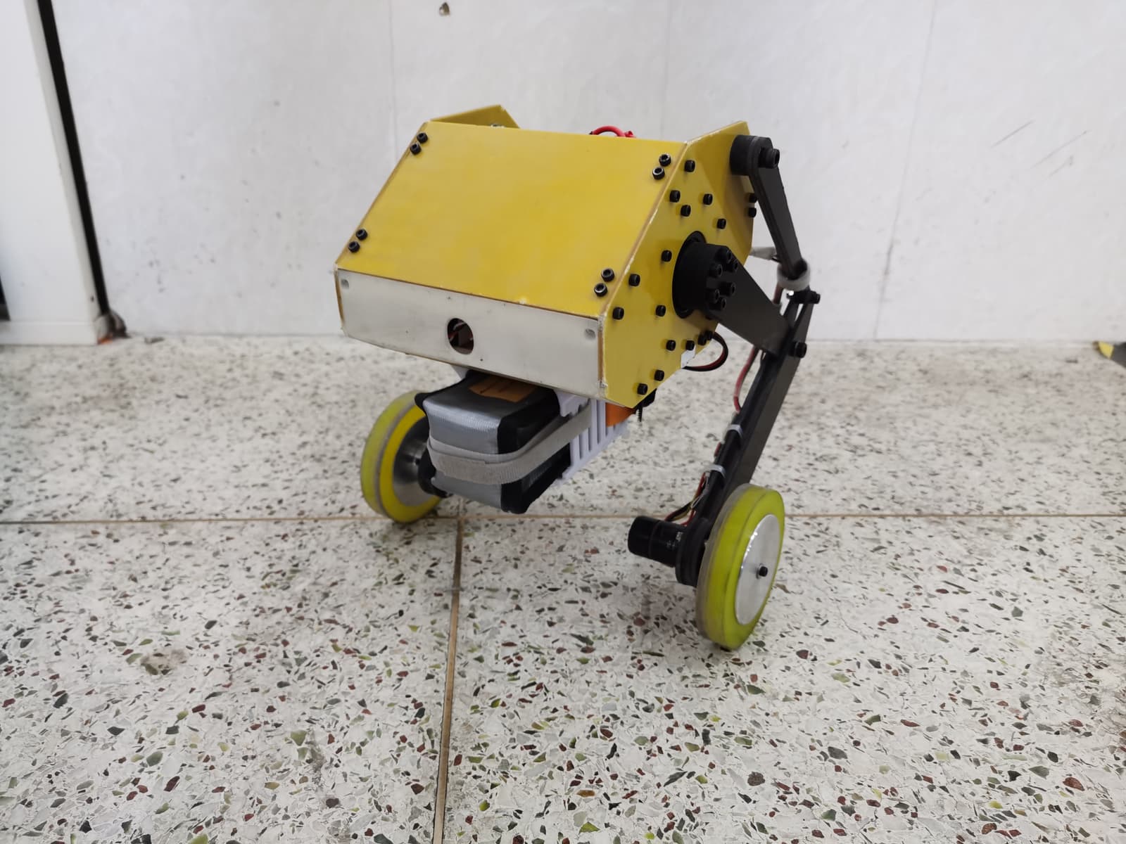
3D preview converted from github.com/track-tech/Venus-1__Four-link-wheel-legged-robot at d64bdc0, under GPL-3.0-only. View the original files from GitHub (358 KB) (opens in a new tab)
What it can do
Written by Robotheca from the project's documents.
- Moves on four wheel-legs with four-link mechanisms
- Self-adaptive center-of-gravity adjustment
- Drop impact buffering
- Active suspension roll-angle stabilization
- Jumping motion
- Remote-controlled via SBUS using FlySky FS-I6X transmitter and FS-IA6B receiver
Bill of materials
This repository has no parts list Robotheca can read yet.
Build guide
The creator's steps, each with its instructions.
- 1Prepare 3D Printed Parts and CAD Models
- 2Assemble Mechanical Structure with 3240 Epoxy Board
- 3Install Joint Motors (CyberGear) and Wheel Motors (DJI C610+M2006)
- 4Mount Electronics and Center Power Distribution Board
- 5Wire and Connect Power and CAN Bus System
- 6Install and Configure STM32H723 with FreeRTOS
- 7Calibrate Motors and Test PID Control
- 8Perform Functional Tests (Adaptive Center of Gravity, Jumping, etc.)
The guide appears here as you scroll.
Guide by @track-tech (README_en.md), under GPL-3.0-only. The English translation is by Robotheca, shared under the same license.
Wiring and electronics
Notes written by Robotheca from the project's documents.
Main parts
- STM32H723 microcontroller board
- Xiaomi CyberGear micro motors for joints (2 units)
- DJI C610 motor driver with M2006 P36 motors for wheels (2 units)
- FlySky FS-IA6B SBUS receiver
- FlySky FS-I6X transmitter
- Central power distribution board with XT60/XT30 connectors and CAN bus splitter
- 24V 35C LiPo battery
Connections
- Power and CAN bus distributed through central power board
- Main controller connected to CyberGear motors via CAN bus
- Wheel motors connected to C610 drivers via CAN bus
- SBUS receiver connected to main controller for remote control
