T-Robot
A DIY omnidirectional mobile robot that supports 2D lidar mapping and autonomous navigation using Micro-ROS and ROS2.
- Wheeled
- Open source
- ROS 2
- 3D printable
Suggested by Robotheca, created by @tianci8 (opens in a new tab), from github.com/tianci8/T-Robot (opens in a new tab). Pinned to commit 51e79ac (opens in a new tab).
- Hardware license
- MIT (opens in a new tab)
- Software license
- MIT (opens in a new tab)
- Commercial use
- Allowed
This repository contains executable files that Robotheca doesn't check. Only run them if you trust the creator.
Photo and 3D model
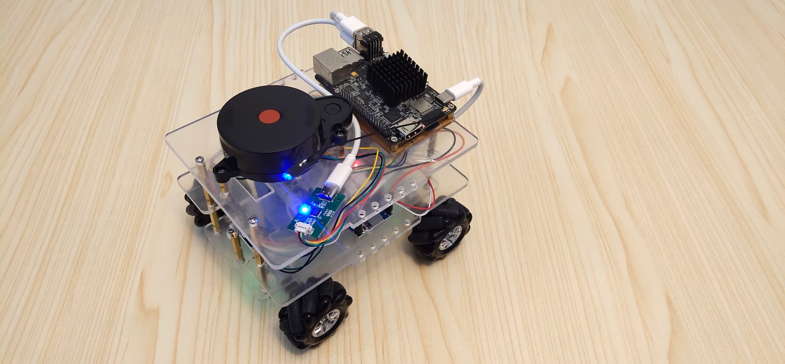
3D preview converted from github.com/tianci8/T-Robot at 51e79ac, under MIT. View the original files from GitHub (16.4 MB) (opens in a new tab)
- Power
- 12 V
What it can do
Written by Robotheca from the project's documents.
- Moves on four mecanum wheels
- Publishes odometry and IMU data over ROS 2
- Subscribes to cmd_vel for velocity commands
- Builds 2D maps with a laser scanner using ROS 2 packages
- Supports autonomous navigation with ROS 2 packages
Bill of materials
This repository has no parts list Robotheca can read yet.
Build guide
The creator's steps, each with its instructions.
- 1Prepare hardware components
- 2Assemble the robot base and structure
- 3Install and configure Micro-ROS firmware on ESP32
- 4Set up ROS2 environment and packages
- 5Configure and test communication between ESP32 and ROS2
- 6Install and calibrate the IMU
- 7Assemble and mount the laser scanner
- 8Configure and test mapping and navigation
- 9Final testing and calibration
The guide appears here as you scroll.
Guide by @tianci8 (README.md), under MIT. The English translation is by Robotheca, shared under the same license.
Wiring and electronics
Notes written by Robotheca from the project's documents.
Main parts
- ESP32 microcontroller board
- Sipeed M1Sense (MangoPi MQ Pro) single-board computer with 2 GB RAM
- LD14 laser scanner
- MPU9250 IMU
- Four WGA12-N20 DC gear motors (12 V, 1:50 reduction)
- Four RZ7889 motor driver chips
- Four AB incremental magnetic hall encoders
- 12 V lithium battery pack
- 12 V to 5 V DC-DC converter (max 4 A)
- Wi-Fi module for communication
Connections
- ESP32 connects to four RZ7889 motor drivers via GPIO pins for PWM and direction control
- ESP32 reads encoder signals from four AB incremental magnetic hall encoders
- ESP32 communicates with MPU9250 IMU via I2C
- ESP32 runs micro-ROS firmware and communicates with the Sipeed board over Wi-Fi
- 12 V battery powers motors directly and the 5 V converter powers ESP32 and Sipeed board