R.O.B.I.N. Ornithopter
A bio-inspired flapping-wing aerial robot for low-disturbance wildlife monitoring, using a transverse crank flapping mechanism, MPU6050 stabilization and RF control.
- Drone
- Open source
- arduino
- 3D printable
Suggested by Robotheca, created by @Degas01 (opens in a new tab), from github.com/Degas01/bio-inspired_ornithopter (opens in a new tab). Pinned to commit 5452951 (opens in a new tab).
- Hardware license
- MIT (opens in a new tab)
- Software license
- MIT (opens in a new tab)
- Commercial use
- Allowed
Photo and 3D model
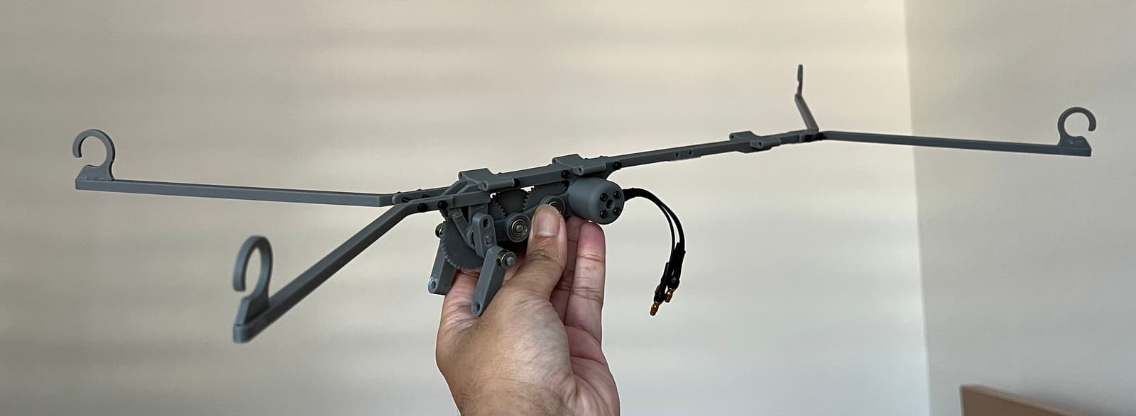
3D preview converted from github.com/Degas01/bio-inspired_ornithopter at 5452951, under MIT. View the original files from GitHub (20.9 MB) (opens in a new tab)
- Reach
- 1,020 mm
- Weight
- 248 g
What it can do
Written by Robotheca from the project's documents.
- Flapping-wing flight driven by a brushless motor through a transverse crank mechanism
- Manual control of motor speed via a potentiometer and tail servo angle via a joystick
- Wireless control over an RF link at 2000bps
- Tail pitch correction using an IMU complementary filter feeding back to the servos
- Glide flight tests with the electronics removed
- Lift testing on a spring scale at varying RPM
Bill of materials
20 parts20 of 20 parts shown
| # | Component | Quantity | Est. price | Supplier |
|---|---|---|---|---|
| 1 | Microcontroller | 2 | – | – |
| 2 | Motor | 1 | – | – |
| 3 | ESC | 1 | – | – |
| 4 | IMU | 1 | – | – |
| 5 | Servos | 2 | – | – |
| 6 | RF Module | 2 | – | – |
| 7 | Battery | 1 | – | – |
| 8 | Joystick | 1 | – | – |
| 9 | Potentiometer | 1 | – | – |
| 10 | BLDC Motor* | 1 | £14≈ €17 | – |
| 11 | ESC* | 1 | £10≈ €12 | – |
| 12 | 2S Battery* | 1 | £6≈ €7 | – |
| 13 | Micro Servos | 2 | £5≈ €6 | – |
| 14 | MPU6050* | 1 | £3≈ €4 | – |
| 15 | PLA Filament | 1 | £14≈ €17 | – |
| 16 | Bearings* | 6 | £2≈ €2 | – |
| 17 | Steel Shafts | 1 | £5≈ €6 | – |
| 18 | Nylon Sheet | 1 | £9≈ €11 | – |
| 19 | PLA Filament | 0.1 | £14≈ €17 | – |
| 20 | Steel Rods | 2 | – | – |
≈ € amounts use the ECB reference rate of 16 Oct 2026, for comparison only.
10 of 20 parts have no price in the source, so there is no parts total. Read from README.md at the pinned commit.
Build guide
The creator's steps, each with its instructions.
- 13D print the flapping mechanism parts in PLA
- 2Cut steel rods and form U-shaped pivots for the wings
- 3Attach the nylon membrane to the wing frames
- 4Follow the circuit diagrams and solder the electronics on perfboard
- 5Mount the components in the body frame
- 6Calibrate the ESC, tail servos and MPU6050
The guide appears here as you scroll.
Guide by @Degas01 (README.md), under MIT.
Wiring and electronics
Notes written by Robotheca from the project's documents.
Main parts
- Arduino Nano controllers, one transmitter and one receiver
- 2300KV brushless DC motor with a 30A ESC
- MPU6050 inertial measurement unit
- Two micro 9g servos for the tail
- RH_ASK 433MHz RF modules
- 2S LiPo battery, 7.4V
- Analog 2-axis joystick and 10kΩ potentiometer
Connections
- Transmitter: potentiometer on analog pin A1, joystick X-axis on A0, RF module TX on digital pin D12, RF RX on D11
- Receiver circuit drives the BLDC motor through its ESC from an Arduino
- MPU6050 and tail servos form a feedback circuit on the receiver side
- Circuit diagrams for the transmitter, receiver motor integration and MPU feedback are in the docs folder


