Quadruped Bai Servo v1
A low-cost 12-DOF quadruped robot actuated by hobby servos, with optional feet sensors and a trot gait firmware.
- Quadruped
- Open source
- arduino
- 3D printable
Suggested by Robotheca, created by @psrobotics (opens in a new tab), from github.com/psrobotics/quadruped_bai_servo (opens in a new tab). Pinned to commit 60c67f2 (opens in a new tab).
- Hardware license
- BSD-3-Clause (opens in a new tab)
- Software license
- BSD-3-Clause (opens in a new tab)
- Commercial use
- Allowed
Photo and 3D model
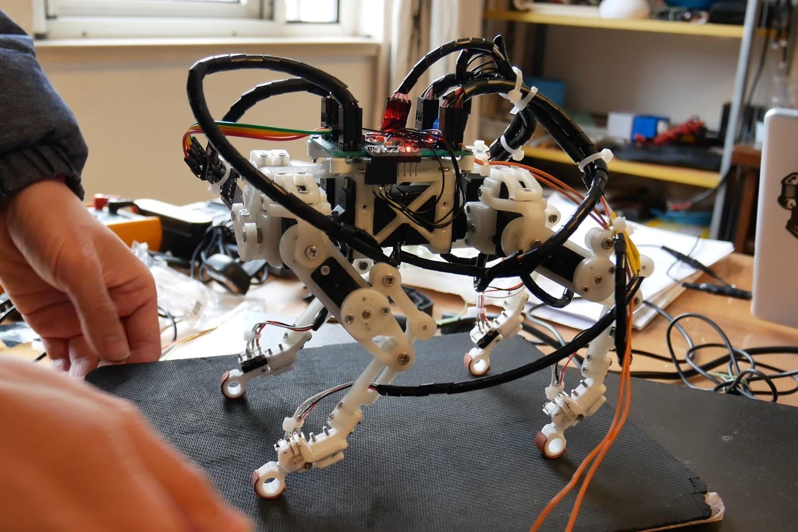
3D preview converted from github.com/psrobotics/quadruped_bai_servo at 60c67f2, under BSD-3-Clause. View the original files from GitHub (5.5 MB) (opens in a new tab)
- Degrees of freedom
- 12
What it can do
Written by Robotheca from the project's documents.
- Walks with a trot gait generated by a simplified state machine that synchronizes open foot trajectories
- Adjusts body roll and pitch during stance phase using IMU feedback
- Balances, as shown in the project's video
- Controlled at the kinematic level only, without resisting external impacts while walking
- Can be wirelessly controlled through an additional serial port connected to a wireless or Bluetooth module
Bill of materials
32 parts32 of 32 parts shown
| # | Component | Quantity | Est. price | Supplier |
|---|---|---|---|---|
| 1 | leg_tip | 2 | – | STL file |
| 2 | leg_tip_MIR | 2 | – | / |
| 3 | leg_2 | 2 | – | / |
| 4 | leg_2_MIR | 2 | – | / |
| 5 | leg_link_1 | 2 | – | / |
| 6 | leg_link_1_MIR | 2 | – | / |
| 7 | leg_link-1 | 2 | – | / |
| 8 | leg_link-1_MIR | 2 | – | / |
| 9 | leg_1 | 2 | – | / |
| 10 | leg_1_MIR | 2 | – | / |
| 11 | leg_1_2 | 2 | – | / |
| 12 | leg_1_2_MIR | 2 | – | / |
| 13 | servo_holder_1 | 2 | – | / |
| 14 | servo_holder_1_MIR | 2 | – | / |
| 15 | hip_joint_holder_1 | 2 | – | / |
| 16 | hip_joint_holder_1_MIR | 2 | – | / |
| 17 | hip_holder_2 | 2 | – | / |
| 18 | hip_holder_2_MIR | 2 | – | / |
| 19 | joint_ab_holder | 2 | – | / |
| 20 | body_bridge | 2 | – | / |
| 21 | body_frame_2 | 1 | – | / |
| 22 | body_frame_1 | 1 | – | / |
| 23 | pcb_holder | 2 | – | / |
| 24 | M3*8 | 20 | – | / |
| 25 | M3*12 | 30 | – | / |
| 26 | M3*16 | 20 | – | / |
| 27 | M2*8 | 50 | – | / |
| 28 | M2*15 | 50 | – | / |
| 29 | M2*20 | 20 | – | / |
| 30 | M2*26 | 20 | – | / |
| 31 | SF-1 0305 Self Lubricating Composite Bearing Bushing Sleeve | 25 | – | ebay: buy SF-1 0305 Self Lubricating Composite Bearing Bushing Sleeve, opens in a new tab |
| 32 | EMAX ES08A II Servo | 12 | – | EMAX: buy EMAX ES08A II Servo, opens in a new tab |
32 of 32 parts have no price in the source, so there is no parts total. Read from README.md at the pinned commit.
Build guide
The creator's steps, each with its instructions.
- 1Print all leg, holder and body parts (infill 70%)
- 2Insert bearings into the 5mm rotation joint holes
- 3Assemble two legs, then two mirrored legs
- 4Link all legs to the body frame
- 5Optionally assemble the micro-switch feet sensors
- 6Add high-friction coating to the feet tips
- 7Pre-calibrate servos with an initial PWM signal before installing
- 8Assemble the controller board, IMU and DC-DC converter module
- 9Mount the battery shelf under the robot frame
- 10Upload firmware via ICSP and tune servo calibration
The guide appears here as you scroll.
Guide by @psrobotics (README.md), under BSD-3-Clause.
Wiring and electronics
Notes written by Robotheca from the project's documents.
Main parts
- 12 EMAX ES08A II analog hobby servos as actuators, one per joint
- Controller board built around an ATmega328P microcontroller with servo controller
- MPU6050 IMU on the controller board
- Integrated boost DC-DC converter module set to 5.5V output to power servos
- Single-cell lithium battery (18650 or 18350) with high current output
- Optional micro switch based feet sensors
Connections
- Controller board connects to the DC-DC converter through a dedicated DC-DC slot
- The DC-DC converter powers the servos
- Hardware IIC pins A4 and A5 are used by the MPU6050 IMU
- An additional serial port on the controller board connects to an optional wireless or Bluetooth module
- Firmware is uploaded through ICSP and debugging uses the external serial port