Project files
4 KB
Machine-translated by Robotheca from the original in Chinese (opens in a new tab). License: MIT (opens in a new tab).
Assembly Guide
1 Insert all heat-set nuts
Tool: soldering iron
M2
Materials: 5 × flange.lua structural parts, 10 × M2×3×3 brass heat-set inserts
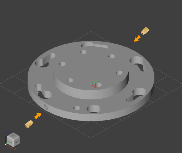
M3
Materials: 6 × shell.lua structural parts, 1 × tail.lua structural part, 1 × base.lua structural part, 1 × elbow.lua structural part, 60 × M3×4×4 heat-melt nuts
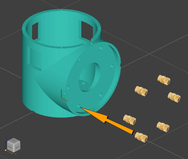 | 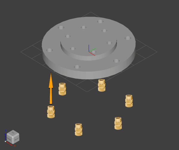 | 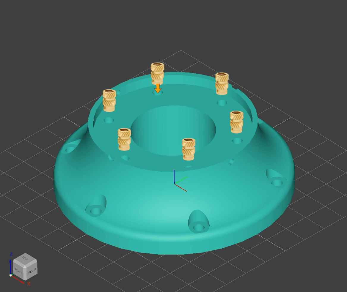 |  |
|---|---|---|---|
| shell | tail | base | elbow |
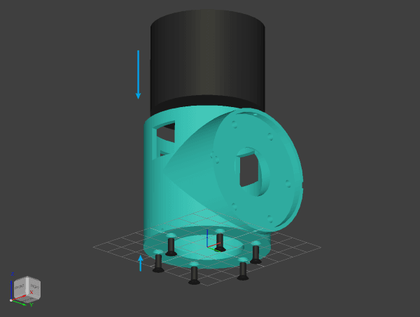
2 Install all motors on the shell
Materials: 6 × shell.lua structural parts, 4 × DM4310 motors, 2 × DM4340 motors, 36 × M3×8 countersunk cross screws
Tools: Cross screwdriver
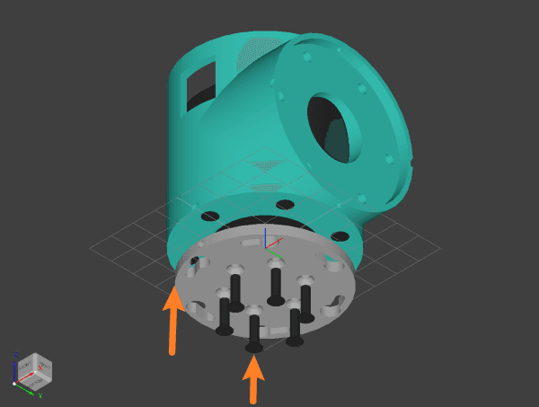
3 Install all flanges onto the motor rotor
Materials: 6 motor-assembled shells, 5 flange.lua structural parts, 1 tail.lua structural part, 36 M3×12 countersunk cross-head screws
Tools: Cross screwdriver
4 Install Joint 1 onto the Base
Materials: 1 × base.lua structural part, 1 × DM4310 joint, 6 × M3*8 hex socket screws, 2 × M2*6 cross flat-head screws
Tools: 5.5 mm open-end wrench, Phillips screwdriver
- Partially thread the
M3*8 hex socket screwsinto the heat-set nuts on thebase.luastructural part. - Align the M2 heat-set nuts on both sides of the flange with the M2 through-holes on the base, then rotate along the arc slot until the large hole aligns with the head of the hex socket screw.
- After all screw heads pass through the joint flange, thread the screws into the arc slot on the flange.
- Insert the two
M2*6 cross flat-head screwsthrough the M2 through-holes on the base and fasten them to the joint. - Use the
5.5 mm open-end wrenchto tighten the screws onto the base.
5 Assembling the Upper Arm
Materials: 2 × DM4340 joints (J2, J3), 1 × linkage.lua (long), 12 × M3×10 socket head screws, 2 × X30 (2+2) wires, several wires, solder, heat-shrink tubing or electrical tape
Tools: soldering iron, hex wrench
- Insert the
X30 (2+2) wiresinto Joint 2, then route the wires through the remaining wire holes above the motor into the shell. - Repeat for Joint 3.
- Insert the four extension wires into the wire holes of the
linkage.lua(long) structural part. - Route each end of the extension wires through the flange slot through-holes of Joint 2 and Joint 3 into the shell, up to the top of the motor.
- Solder all wires.
- Secure Joint 2 and Joint 3 to the
linkage.lua(long) structural part using M3×10 socket head screws; ensure that the joint axes are aligned in the same direction.
6 Install the upper arm to Joint 1
Materials: 1 main body, 1 upper arm, 6 × M3×8 hex socket screws, 2 × M2×6 cross flat-head screws
Tools: 5.5 mm open-end wrench, cross-head screwdriver
Install Joint 2 onto Joint 1 using the same steps as when you installed Joint 1 onto the base.
Note: The M2 screws at the bottom of Joint 1 are hard to reach; installing the top screws is sufficient.
7 Assembling the Forearm
Materials: 1 DM4310 joint (J4), 1 elbow.lua, 1 linkage.lua (short), 12 M3×10 hex socket screws, 2 X30 (2+2) wires, several wires, solder, heat-shrink tubing or electrical tape
Tools: soldering iron, hex wrench
- Insert the
X30 (2+2) wiresinto joint 4, then route the wires through the remaining wire hole above the motor into the shell. - Insert the 4 extension wires into the wire holes of the
linkage.lua(short) structural part. - Route one end of each extension wire through the through-holes in the flange slot of joint 4 into the shell, up to the top of the motor; route the other end through the square hole on the side of the
elbow.luastructural part. - Solder all wires.
- Use the M3×10 hex socket screws to secure joint 4 and the
elbow.luastructural part to thelinkage.lua(short) structural part, paying attention to the two axial directions.
8 Install the forearm to joint 3
Materials: current body 1, forearm 1, external hexagon screw M3*8 6, cross flat-head screw M2*6 2
Tools: open-end wrench 5.5 mm, Phillips screwdriver
Install the elbow to joint 3; the steps are the same as installing joint 1 to the base
9 Install Joint 5 and Joint 6
Materials: Current body 1, DM4310 joint (J5 J6) 2, M3*8 hex socket screws 12, M2*6 cross flat head screws 4
Tools: 5.5 mm open-end wrench, Phillips screwdriver
- Install Joint 5 onto Joint 4 using the same steps as when installing Joint 1 onto the base.
- Install Joint 6 onto Joint 5 using the same steps as when installing Joint 1 onto the base.
Files by @Jelatine, at commit a0e2f59, read from GitHub in your browser. Hardware license: MIT; software license: MIT. Robotheca doesn't review code: read it before running it.