Project files
7 KB
Machine-translated by Robotheca from the original in Chinese (opens in a new tab). License: MIT (opens in a new tab).
05 — Structural Assembly and Wiring Guide
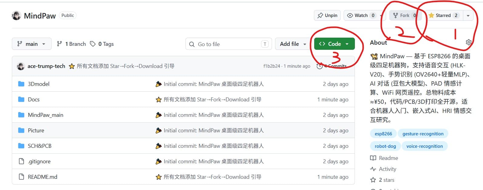
⭐ Before using this tutorial, please support this open-source project:
- Star ⭐ — Click the ⭐ Star in the top-right corner of the GitHub repository to bookmark this project for easy future access
- Fork 🍴 — Click Fork to copy the project to your GitHub account, allowing you to modify it freely
- Download 📥 — Click the green Code button → Download ZIP to download it locally and start building
📸 Operation diagram:
3D-printed Parts Assembly
Parts List
| Printed Part | Quantity | Description |
|---|---|---|
body.stl | 1 | Main body |
bottom.stl | 1 | Chassis |
foot.stl | 4 | Foot (one per leg) |
Assembly Steps
Step 1: Install the Base
- Place
bottom.stlflat on the work surface. - Install the 4 servos into the pre-cut slots on the base.
- Secure with screws (M2 screws recommended).
Step 2: Assemble the Body
- Align
body.stlwith the base. - Fasten the two parts together from the bottom using screws.
- Route the wiring through the internal cavity of the body.
Step 3: Install the Feet
- Attach the 4
foot.stlparts to the servo arms. - Adjust each foot to the initial angle (90 degrees).
Circuit Wiring Diagram
                         +5V (direct battery supply)
                          │
    ┌─────────────────────┼──────────────────────────┐
    │                     │                          │
Servo1~4 red wire → 5V    Speaker + PIN       HLK-V20
                   ┌────┤ NPN                      │
                   │ 1KΩ│ Triode                    │
GPIO16(D0) ────────┘    │ E                         │
                         │ GND                       │
ESP12F                                               │
┌────────────────────────────────────────────────────┤
│                                            GPIO0 ──┤← HLK-V20 TX
│ GPIO14 ──1KΩ── Servo1 + OV2640_SCK                │
│ GPIO12 ──1KΩ── Servo3 + OV2640_MISO               │
│ GPIO13 ──1KΩ── Servo4 + OV2640_MOSI               │
│ GPIO15 ──▶ OV2640_CS + 10KΩ↓GND (⚠ must!)         │
│ GPIO16 ──▶ Speaker (triode drive)                 │
│ GPIO0  ──▶ HLK-V20 TX (SoftwareSerial RX)         │
│ GPIO2  ──◀ Button 1 → GND (INPUT_PULLUP)          │
│ GPIO4  ──▶ OLED SDA (I2C)                         │
│ GPIO5  ──▶ OLED SCL (I2C)                         │
│ A0     ──▶ Voltage divider → Battery+             │
│ TX(GPIO1) → USB-TTL RX (debug port)               │
│ RX(GPIO3) → USB-TTL TX (debug port)               │
└────────────────────────────────────────────────────┘
Detailed Wiring of Each Module
Servos ×4
| Servo | ESP12F | Servo Wires (Orange/Red/Brown) |
|---|---|---|
| Servo 1 | GPIO14 (D5) — Signal | Orange ← GPIO14, Red ← 5V, Brown ← GND |
| Servo 2 | GPIO16 (D0) — Signal | Orange ← GPIO16, Red ← 5V, Brown ← GND |
| Servo 3 | GPIO12 (D6) — Signal | Orange ← GPIO12, Red ← 5V, Brown ← GND |
| Servo 4 | GPIO13 (D7) — Signal | Orange ← GPIO13, Red ← 5V, Brown ← GND |
⚠️ Connect all servo red wires to 5V battery direct supply (do not connect to ESP's 3.3V!)
OLED Display (SSD1306, I2C)
| OLED Pin | Connect to ESP12F |
|---|---|
| GND | GND |
| VCC | 3.3V |
| SCL (Clock) | GPIO5 (D1) — 4.7KΩ pull-up |
| SDA (Data) | GPIO4 (D2) — 4.7KΩ pull-up |
OV2640 Camera (ArduCAM Mini, SPI)
| OV2640 Pin | Connected to ESP12F |
|---|---|
| CS | GPIO15 (D8) — 10KΩ pull-down to GND |
| SCK | → 1KΩ → GPIO14 (D5) — shared with Servo 1 |
| MISO | → 1KΩ → GPIO12 (D6) — shared with Servo 3 |
| MOSI | → 1KΩ → GPIO13 (D7) — shared with Servo 4 |
| VCC | 3.3V |
| GND | GND |
HLK-V20 Voice Module (UART)
| HLK-V20 Pin | Connect to ESP12F |
|---|---|
| TX | GPIO0 (D3) — SoftwareSerial RX |
| RX | Leave unconnected (only used during PC configuration via USB-TTL) |
| VCC | 3.3V ~ 5V |
| GND | GND |
Speaker (Transistor Driven)
                    +5V
                     │
                    ╱
                  ╱ Speaker (8Ω/0.5W)
                  ╲
                    │
                    │  C
GPIO16 ──[1KΩ]───── B  NPN (S8050/2N2222)
                      E
                      │
                     GND
Power Supply Solutions
MindPaw supports two power supply methods:
Option A: USB Power (Recommended, ¥0)
This is the most cost-effective method, using a phone charger + MicroUSB cable:
Phone charger (5V/1A+) ── MicroUSB cable ── ESP12F development board USB port
                                    │
                                AMS1117 regulated to 3.3V
                                    │
                            ┌───────┴───────┐
                            │               │
                         Servo 5V          OLED/OV2640/HLK-V20 3.3V
| Requirement | Description |
|---|---|
| Charger | Phone charger with 5V / 1A or higher (any Android charger works) |
| Data cable | Standard MicroUSB cable (note: must be a data cable, not a pure charging cable) |
| Servo power | The 5V from the development board's USB port directly powers the servos (red wire) |
⚠ SG90 servo stall current ~700mA, peak current for 4 servos ~2.8A. It is recommended to use a charger with 5V/2A or higher. If the servos stall, try a charger with higher current. During normal walking, average current is ~500mA, so a standard phone charger is sufficient.
Option B: Battery Power (Optional, ¥30+)
When mobile use (without a wired connection) is required, add a 2S lithium battery:
| Module | Power Supply | Voltage |
|---|---|---|
| ESP12F | Regulated via AMS1117 | 3.3V |
| Servo ×4 | Direct from battery | 5V ~ 8.4V |
| OLED | 3.3V output from ESP12F | 3.3V |
| OV2640 | 3.3V output from ESP12F | 3.3V |
| HLK-V20 | 3.3V output from ESP12F | 3.3V~5V |
Battery Voltage Divider Circuit (ADC Detection):
Battery+ (8.4V max) ── R1 (100KΩ) ──┬── A0 (ESP12F)
                                    │
                                R2 (12KΩ)
                                    │
                                   GND
💡 Money-saving tip: Use the tea-brewing base or USB power for development and debugging first. Once everything is working, decide whether to add the battery.
⚠️ Key Notes
Prerequisites for Booting
| Pin | Boot State | If Not Met |
|---|---|---|
| GPIO0 | Must be HIGH (or floating) | Module enters download mode |
| GPIO15 | Must be pulled down to GND with 10KΩ | Module fails to boot |
| GPIO2 | Must be HIGH (internally pulled up) | Serial port initialization exception |
Debugging Tips
- First Power-On: Connect only the ESP12F + USB-TTL first, and confirm that the serial port outputs logs.
- Servo Not Moving: Check if the 5V power supply is normal and if the servo signal wires are connected correctly.
- OLED Not Lighting Up: Check the I2C pull-up resistors (4.7KΩ) and confirm the address is 0x3C.
- HLK-V20 Not Responding: Use a USB-TTL to connect to the module and confirm that the configuration has been flashed.
- OV2640 Not Working: Check the GPIO15 pull-down resistor and the 1KΩ resistor shared with SPI.
Files by @ace-trump-tech, at commit 21c5492, read from GitHub in your browser. Hardware license: MIT; software license: MIT. Robotheca doesn't review code: read it before running it.